
Related Manuals for digico SD7


Summary of Contents for digico SD7
- Page 1 SD7 Operation Manual User Manual - Getting Started To be read in conjunction with the SD Series Software Reference User Manual Version D for Software Versions 4.0.680+...
-
Page 2: Sd7 Operation Manual
Licenses and Trademarks The SD7 logo and SD7 name are trademarks, and Digico UK Ltd and the Digico UK Ltd logo are registered trademarks of Digico UK Ltd. Microsoft is a registered trademark and Windows is a trademark of Microsoft Corp. -
Page 3: Table Of Contents
SD7 Operation Manual Contents 1.1 The Console ..................1-1 1.2 Manual Overview ................1-1 1.3 Before You Start ................1-2 1.3.1 Worksurface Layout .............1-2 1.3.2 Layers and Banks ..............1-3 1.3.3 Using the Control Surface ...........1-3 1.3.4 The Assigned Channel ............1-4 1.3.5 The Master Fader ............ - Page 4 SD7 Operation Manual 1.12 Multi-channel formats..............1-24 1.13 Solo Setup..................1-25...
-
Page 5: The Console
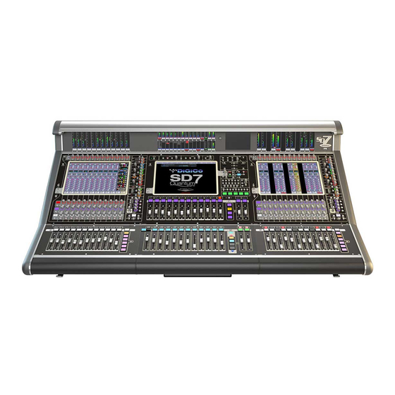
1.1 The Console The Digico SD7 consists of a worksurface with dual redundant audio engines and a range of onboard inputs and outputs. This can be connected to multiple Input/Output Rack Units by optical fibre and/or MADI links, which carry all the audio input and output signals. -
Page 6: Before You Start
SD7 - Getting Started 1.3 Before You Start There are certain general operating principles and terms that should be understood before continuing to use this manual. Please read this chapter carefully before proceeding. 1.3.1 Worksurface Layout.............. Left & Right Sections... -
Page 7: Layers And Banks
1.3.2 Layers and Banks ..............The SD7's worksurface is divided into Layers and Banks. Each Bank contains twelve channels, and the channels which are currently active on the control surface are defined using the fader bank and bank layer buttons to the right of the Channel Strip section’s faders:... -
Page 8: The Assigned Channel
SD7 - Getting Started To the right of the Master Panel is a single encoder marked Touch-Turn (shown below). This is used to access any rotary controls within the Master Panel. To assign the Touch-Turn encoder to a particular on-screen pot, touch the pot to be assigned. -
Page 9: The Master Fader
SD7 - Getting Started The controls to the right of the Channel Strip panel allow the Assigned channel to be adjusted: The top half of the channel worksurface controls (down as far as the insert a, insert b and direct buttons, as shown above) control the signal processing parameters which are displayed in the pop-ups accessed by touching in the appropriate section of the active channel. -
Page 10: Channel Types
SD7 - Getting Started 1.3.6 Channel Types ..............The SD7 has 4 different channel types which are laid out in banks of 12 on the console worksurface and can be identified by their colour. By default, the Input Channels will be assigned to Layer 1 on the left and right sections of the console. -
Page 11: Hardware Configuration
The SD7 worksurface has 12 analogue I/O and 12 AES I/O on its rear panel (referred to as Local I/O) and additional I/O is supplied in the form of remote Racks which can each accommodate up to 56 inputs and 56 outputs in different formats. These racks are connected to the worksurface by either 100M high specification 75 Ohm coaxial cables fitted with BNC connectors or optical fibre. -
Page 12: Software Configuration
1.5 Software Configuration The SD7 has a default setup which means that the new user need not get involved in configuring the desk at this stage. However, here is a brief overview of how the different displays are used in putting together a session. Each of the master displays intro- duced below are described fully within the rest of the manual. -
Page 13: Audio I/O Overview
Pads and phantom power. Local I/O : The SD7 provides local audio I/O via 3 cards installed in the rear of the console. These operate independently of connected racks, providing additional audio I/O. -
Page 14: Opto V220 (Digiracks) And Opto V221 (Sd Racks)
1.5.6 Network & Mirroring ............. The SD7 console is fitted with two separate Engines, and as such, offers built in redundancy. In order to take advantage of this redundancy, you need to verify the console networking is working, and synchronise your session between the two Engines. -
Page 15: Single Sd Console System
Second console B Engine = OPTO ID 3 - This engine cannot output to Optocore racks For Optocore V221: SD7 console engines are numbered in pairs eg 1&2 or 3&4 and up to 5 pairs (5 x SD7 consoles) can be connected at the same time. -
Page 16: Manual Conforming Of Racks
Standard MADI Connections If you have a standard MADI connection (not a DiGiCo Rack) to your SD7, you can set the console to display the MADI with generic signal names, i.e. MADI 1, MADI 2.. etc. through to MADI 56 (or 64) instead of the usual rack style names. The naming does not affect the signal, but makes routing signals easier. -
Page 17: Rack Sharing
Receive Only : The SD7 will receive the rack’s existing settings but will not be able to control the gain etc on the racks. Full Control : The SD7 will send its settings to the racks and change them accordingly. -
Page 18: Assigning Faders To The Worksurface
SD7 - Getting Started 1.5.10 Assigning Faders to the Worksurface........ If, after a Session Restructure, you find that newly created channels do not appear on the worksurface, open the Layout/ Channel List panel on the Master screen and you will see a full list of all input and output channels that are present in the session. -
Page 19: Saving And Loading Sessions
SD7 - Getting Started 1.6 Saving and Loading Sessions 1.6.1 Save As New File ..............When you change the configuration of a session you should save it to the console's flash drive under a new filename. If the Save Session panel has not appeared automatically after a session restructure then touch the Files button on the Master screen and then press Save As New File. -
Page 20: Audio Sync
Optocore as their sync source. Example Clocking from Optocore@ 96kHz There are also times when the SD7 needs to be clocked externally. The Audio Sync panel allows you to control external synchro- nisation. The SD7 will clock from the following sources : Word Clock, AES/EBU, Video Reference, MADI & Optocore In this situation one Optocore device should be set to clock to the external source and all other Optocore devices should be set to sync to Optocore. -
Page 21: Routing Basics
For input and insert return routing, the INTERNAL port provides the following signal groups: Misc: The oscillator, white and pink noise generators. Graphic EQs: The outputs of the SD7’s internal graphic EQ’s. Effects: The outputs of any effects sends that have been created... -
Page 22: Ripple Channels
For output and insert send routing, the INTERNAL port provides access to the inputs of the SD7’s Graphic EQ’s, and the inputs to any effects that have been created. -
Page 23: Channel Processing
SD7 - Getting Started 1.9 Channel Processing 1.9.1 Dynamic EQ ................The EQ section comprises four user-configurable parametric filters with Dynamic Control and a pair of swept High-pass and Low- pass filters. The EQ is accessed by touching the on screen display to Assign the channel (the colour changes to yellow) and then using the controls on the right hand side of the input module. -
Page 24: Multiband Dynamics
SD7 - Getting Started 1.9.2 Multiband Dynamics ............. The dynamics are accessed by touching the words Comp or Gate just below the EQ graph on screen to open the dynamics panel. There are two dynamics modules, the first of which can function as a simple compressor, a 3 way multiband compressor, or a de-esser, according to the comp/multi/desser button to its left. -
Page 25: Auxiliaries
SD7 - Getting Started 1.9.3 Auxiliaries ................The auxiliaries can be accessed by touching the auxiliary row on screen or using the Screen Scroll buttons on the left of the worksurface Using either of these methods, the highlighted auxiliaries on the input screen will change. The rotary controls and switches beneath the screen are used as auxiliary sends, pans (with 2nd Function ON), On/Off and pre/post switches (with 2nd Function ON). -
Page 26: The Matrix
To open the Matrix Inputs panel, touch the Matrix button on the Master Screen Menu. The window that opens allow you to route inputs to the Matrix Output Channels, and set the Matrix crosspoint levels. To route an input, touch the top of the appropriate Matrix column. This opens a standard SD7 input routing page. Matrix Input Routing... -
Page 27: Control Groups
SD7 - Getting Started 1.11 Control Groups Any number of input channels and output channels can be connected to one or more of the 36 possible Control Groups. They can then all be operated from a single worksurface control. Changes to the Control Group fader, mute or solo or controls will affect all channels connected to the group. -
Page 28: Multi-Channel Formats
SD7 - Getting Started 1.12 Multi-channel formats If you are working in Surround, or using another multi-channel format, you can create LCR, LCRS and 5.1 busses in the Session Structure window described in Section 1.5.1. Multi-channel inputs are controlled by routing each component througha mono channel and then linking those channels via a 'Multi' channel. -
Page 29: Solo Setup
SD7 - Getting Started 1.13 Solo Setup The SD7 Solo panel is accessed from a button at the top of the Master Screen. Some of the controls on this panel are duplicated on the worksurface, immediately above the Master Screen. - Page 30 SD7 - Getting Started 1-26...
Need help?
Do you have a question about the SD7 and is the answer not in the manual?
Questions and answers