Advertisement
Quick Links
SERVICE MANUAL
REVISED
Ver 1.2 1999. 09
MICROFILM
SPECIFICATIONS
Amplifier
Power output
3 W + 3 W
Input impedance
4.7 kΩ (at 1 kHz)
Stereo mini jack × 2 (INPUT1, 2)
Input
Approx. 140 × 40 × 140 mm
Dimensions
× 1
× 5
5
5
(5
/
/
8
8
Mass
Approx. 590 g 1lb 5 oz
Speakers
System
Full-range, bass reflex type
Speaker unit
Magnetically shielded ø39 mm
9
(1
/
inch)
16
Nominal Impedance 8 Ω
Rated input power
3 W
Approx. 80 × 176 × 80 mm
Dimensions
× 7 × 3
(3
1
/
1
/
4
Mass
Approx. 380 g 13 oz
General
Power requirement
DC IN 9 V jack accepts the supplied
Sony AC power adaptor
Supplied accessories AC power adaptor (1)
Connecting cord
(stereo miniplug ↔ stereo miniplug) (1)
Design and specifications are subject to change without notice.
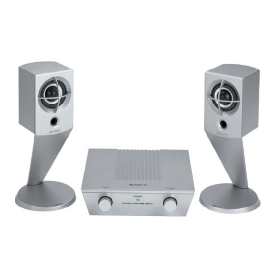
STEREO ACTIVE SPEAKER SYSTEM
SRS-Z1
Canadian Model
Australian Model
5
/
in.) (w/h/d)
8
in.) (w/h/d)
4
US Model
AEP Model
UK Model
E Model
Tourist Model
Advertisement

Related Manuals for Sony SRS-Z1


Summary of Contents for Sony SRS-Z1
- Page 1 Approx. 380 g 13 oz General Power requirement DC IN 9 V jack accepts the supplied Sony AC power adaptor Supplied accessories AC power adaptor (1) Connecting cord (stereo miniplug ↔ stereo miniplug) (1) Design and specifications are subject to change without notice.
- Page 2 DIAGRAMMES SCHÉMATIQUES ET LA LISTE DES PIÈCES SONT LIST ARE CRITICAL TO SAFE OPERATION. REPLACE THESE CRITIQUES POUR LA SÉCURITÉ DE FONCTIONNEMENT. NE REMPLACER CES COMPOSANTS QUE PAR DES PIÈSES SONY COMPONENTS WITH SONY PARTS WHOSE PART NUMBERS APPEAR AS SHOWN IN THIS MANUAL OR IN SUPPLEMENTS DONT LES NUMÉROS SONT DONNÉS DANS CE MANUEL OU...
- Page 3 SECTION 2 DIAGRAMS 2-1. IC BLOCK DIAGRAM • IC1, IC2 TEA2025B FEED OUT1 BOOT1 IN1+ BACK THERMAL PROTECT. START CIRCUIT DECOUPLING BRIDGE OUT2 BOOT2 FEED IN2+ BACK Note on Printed Wiring Board: • X : parts extracted from the component side. •...
- Page 4 SRS-Z1 2-2. PRINTED WIRING BOARD • Refer to page 3 for Note on Printed Wiring Board. M AIN BO ARD (POWER) LED BO ARD D101 DC IN 9V (POWER) (11) 1-673-372- INPUT D2 D1 (CHASSIS) SP OUT L 16 15...
- Page 5 SRS-Z1 2-3. SCHEMATIC DIAGRAM • Refer to page 3 for IC Block Diagram and Note on Schematic Diagram. — 5 — — 6 —...
- Page 6 SECTION 3 EXPLODED VIEWS NOTE: 3-2. SPEAKER SECTION • Items marked “*” are not stocked since they • The mechanical parts with no reference number are seldom required for routine service. Some in the exploded views are not supplied. delay should be anticipated when ordering these items.
-
Page 7: Electrical Parts List
SECTION 4 MAIN ELECTRICAL PARTS LIST NOTE: • Due to standardization, replacements in the • CAPACITORS: • SEMICONDUCTORS parts list may be different from the parts uF: µF In each case, u: µ, for example: specified in the diagrams or the components •... - Page 8 SRS-Z1 MAIN Ref. No. Part No. Description Remarks Ref. No. Part No. Description Remarks 1-249-429-11 CARBON 1/4W MISCELLANEOUS 1-249-417-11 CARBON 1/4W F ************** 1-249-416-11 CARBON 1/4W F 1-769-080-41 CORD (WITH PLUG) 1-247-843-11 CARBON 3.3K 1/4W ************************************************************ 1-249-407-11 CARBON 1/4W F ACCESSORIES &...
Need help?
Do you have a question about the SRS-Z1 and is the answer not in the manual?
Questions and answers