Table of Contents
Advertisement
Quick Links
Service
Manual
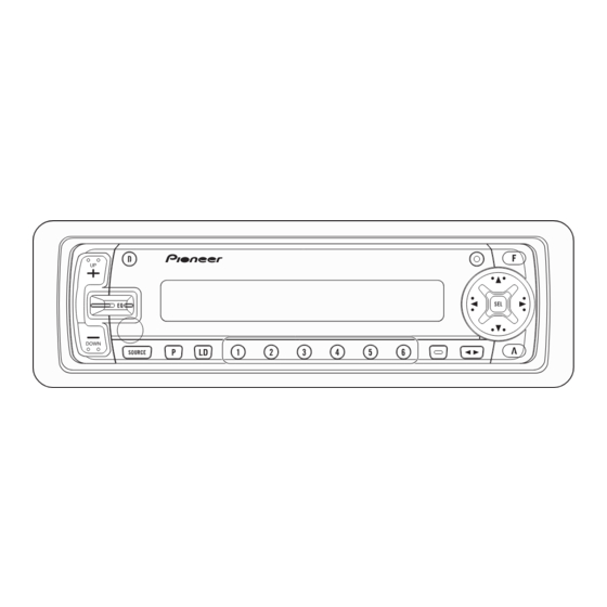
MULTI-CD CONTROL HIGH POWER CASSETTE PLAYER WITH FM/AM TUNER
KEH-P7850
NOTE:
- See the separate manual CX-631(CRT1640) for the cassette mechanism description.
- The cassette mechanism assy employed in this model is one of 2L series.
- Dolby noise reduction manufactured under license from Dolby Laboratories Licensing Corporation.
"Dolby" and the double-D symbol are trademarks of Dolby Laboratories Licensing Corporation.
CONTENTS
1. SAFETY INFORMATION ...........................................2
2. EXPLODED VIEWS AND PARTS LIST......................2
3. SCHEMATIC DIAGRAM ..........................................10
4. PCB CONNECTION DIAGRAM ...............................20
5. ELECTRICAL PARTS LIST .......................................30
6. ADJUSTMENT ........................................................36
PIONEER ELECTRONIC CORPORATION
PIONEER ELECTRONICS SERVICE INC.
PIONEER ELECTRONIC [EUROPE] N.V.
PIONEER ELECTRONICS ASIACENTRE PTE.LTD. 253 Alexandra Road, #04-01, Singapore 159936
C PIONEER ELECTRONIC CORPORATION 1998
4-1, Meguro 1-Chome, Meguro-ku, Tokyo 153-8654, Japan
P.O.Box 1760, Long Beach, CA 90801-1760 U.S.A.
Haven 1087 Keetberglaan 1, 9120 Melsele, Belgium
7. GENERAL INFORMATION ......................................38
7.1 PARTS.................................................................38
7.1.1 IC ...............................................................38
7.1.2 DISPLAY ...................................................43
7.2 DIAGNOSIS........................................................44
7.2.1 DISASSEMBLY .........................................44
7.2.2 TEST MODE .............................................45
7.3 BLOCK DIAGRAM..............................................48
8. OPERATIONS AND SPECIFICATIONS ...................49
K-ZZS. NOV. 1998 Printed in Japan
ORDER NO.
CRT2307
X1N/ES
Advertisement
Table of Contents

Subscribe to Our Youtube Channel
Related Manuals for Pioneer KEH-P7850


Summary of Contents for Pioneer KEH-P7850
-
Page 1: Table Of Contents
PIONEER ELECTRONICS SERVICE INC. P.O.Box 1760, Long Beach, CA 90801-1760 U.S.A. PIONEER ELECTRONIC [EUROPE] N.V. Haven 1087 Keetberglaan 1, 9120 Melsele, Belgium PIONEER ELECTRONICS ASIACENTRE PTE.LTD. 253 Alexandra Road, #04-01, Singapore 159936 C PIONEER ELECTRONIC CORPORATION 1998 K-ZZS. NOV. 1998 Printed in Japan... -
Page 2: Safety Information
KEH-P7850 1. SAFETY INFORMATION This service manual is intended for qualified service technicians; it is not meant for the casual do-it-yourselfer. Qualified technicians have the necessary test equipment and tools, and have been trained to properly and safely repair complex products such as those covered by this manual. - Page 3 KEH-P7850 NOTE: - Parts marked by “*” are generally unavailable because they are not in our Master Spare Parts List. ∇ mark on the product are used for disassembly. - Screws adjacent to PACKING SECTION PARTS LIST Mark No. Description Part No.
- Page 4 KEH-P7850 2.2 EXTERIOR...
- Page 5 KEH-P7850 (1) EXTERIOR SECTION PARTS LIST Mark No. Description Part No. Mark No. Description Part No. 1 Screw BMZ30P040FMC 46 Insulator CNM6190 2 Screw BSZ26P050FMC 47 Insulator CNM6257 3 Screw BSZ30P050FMC 48 Heat Sink CNR1505 4 Cord Assy CDE5758 49 Insulator...
- Page 6 KEH-P7850 Mark No. Description Part No. 91 Holder CNS5165 92 Holder CNS5389 93 Switch(S602) CSN1027 94 Holder Unit CXB3049 95 Holder Unit CXB3050 96 Holder Unit CXB3051 97 Damper Unit CXB3180 98 Screw IMS20P040FZK 99 Remote Control Unit CXB3456 100 Cover CNS4948 101 •••••...
- Page 7 KEH-P7850...
- Page 8 KEH-P7850 2.3 CASSETTE MECHANISM MODULE...
- Page 9 KEH-P7850 - CASSETTE MECHANISM MODULE SECTION PARTS LIST Mark No. Description Part No. Mark No. Description Part No. 1 Screw BSZ20P040FMC 31 Gear ENV1347 2 Washer CBF1037 32 Collar ENV1508 3 Washer CBF1038 33 Gear ENV1350 4 Washer CBG1003 34 Flywheel...
-
Page 10: Schematic Diagram
KEH-P7850 3. SCHEMATIC DIAGRAM 3.1 OVERALL CONNECTION DIAGRAM (GUIDE PAGE) Note: When ordering service parts, be sure to refer to “EXPLODED VIEWS AND PARTS LIST” or “ELECTRICAL PARTS LIST”. ANTENNA JACK Large size SCH diagram Guide page Detailed page... - Page 11 KEH-P7850...
- Page 12 KEH-P7850...
- Page 13 KEH-P7850 A-a C...
- Page 14 KEH-P7850...
- Page 15 KEH-P7850...
- Page 16 KEH-P7850 3.2 FM/AM TUNER UNIT FM/AM TUNER UN...
- Page 17 KEH-P7850 ER UNIT...
-
Page 18: Cassette Mechanism Module
KEH-P7850 3.3 CASSETTE MECHANISM MODULE DECK UNIT VR302 CCP1280 33K(B) C256 R258 C253 330P R283 0R0 R256 220 R273 C254 330P R284 0R0 R272 R271 R290 R282 0R0 R274 C273 CXA2560Q C252 330P R287 22/16 C403 R281 0R0 R403 82... - Page 19 KEH-P7850 PCB UNIT MOTOR UNIT (MAIN MOTOR) EXA1490 LOAD R373 70µs ESG1004 R375 ESG1004 R290 MODE SENSE C403 R068 EGN1 R403 82K EGN1005 C402 R402 4700P C401 R401 4R7K MOTOR UNIT (SUB MOTOR) EXA1485 EGN2 EGN3 R374 EGN1006 EGN1006 FWD END...
-
Page 20: Pcb Connection Diagram
KEH-P7850 4. PCB CONNECTION DIAGRAM TUNER AMP UNIT 4.1 TUNER AMP UNIT CORD ASSY CORD NOTE FOR PCB DIAGRAMS 1. The parts mounted on this PCB include all necessary parts for several destination. For further information for respective destinations, be sure to check with the schematic dia- gram. - Page 21 KEH-P7850 SIDE A CORD PRE OUT IP BUS IN ANTENNA CN251 S602 DOOR CN901...
- Page 22 KEH-P7850 TUNER AMP UNIT...
- Page 23 KEH-P7850 SIDE B...
- Page 24 KEH-P7850 4.2 KEYBOARD UNIT SIDE A...
- Page 25 KEH-P7850 SIDE B...
- Page 26 KEH-P7850 4.3 FM/AM TUNER UNIT SIDE A...
- Page 27 KEH-P7850 SIDE B...
- Page 28 KEH-P7850 4.4 CASSETTE MECHANISM MODULE DECK UNIT SIDE A CN602 DECK UNIT SIDE B HEAD ASSY...
- Page 29 KEH-P7850 PCB UNIT SIDE A LOAD SW EGN1 MODE SENSE 70µ SW PCB UNIT SIDE B CN253 1 2 3 4 5 6 REEL PCB...
-
Page 30: Electrical Parts List
KEH-P7850 5. ELECTRICAL PARTS LIST NOTE: - Parts whose parts numbers are omitted are subject to being not supplied. - The part numbers shown below indicate chip components. Chip Resistor RS1/_S___J,RS1/__S___J Chip Capacitor (except for CQS..) CKS.., CCS.., CSZS..=====Circuit Symbol and No.===Part Name Part No. - Page 31 KEH-P7850 =====Circuit Symbol and No.===Part Name Part No. =====Circuit Symbol and No.===Part Name Part No. ------ ------------------------------------------ ------------------------- ------ ------------------------------------------ ------------------------- CAPACITORS CKSQYB104K16 CCSRCH101J50 CCSQCH6R0D50 CEJA470M6R3 CCSRCK2R0C50 CKSRYB103K25 CCSRCH820J50 CCSRCH101J50 CCSRCH820J50 CKSRYB103K25 CEJA1R5M50 CCSRCH471J50 CKSQYB104K16 CKSRYB103K25 CCSRCKR50C50 CKSRYB103K25 CEJA1R0M50 CCSRCH330J50...
- Page 32 KEH-P7850 =====Circuit Symbol and No.===Part Name Part No. =====Circuit Symbol and No.===Part Name Part No. ------ ------------------------------------------ ------------------------- ------ ------------------------------------------ ------------------------- Transistor 2SA1674 RS1/10S222J Transistor 2SA1048 RS1/10S562J Transistor DTC114TU RS1/10S821J Transistor DTC114TU RS1/10S821J Transistor 2SC4081 RS1/10S821J Transistor DTC114TU RS1/10S821J Transistor...
- Page 33 KEH-P7850 =====Circuit Symbol and No.===Part Name Part No. =====Circuit Symbol and No.===Part Name Part No. ------ ------------------------------------------ ------------------------- ------ ------------------------------------------ ------------------------- RS1/10S751J RS1/8S474J RS1/10S473J RS1/8S105J RD1/4PU102J RD1/2PM182J RS1/10S103J RD1/2PM182J RS1/10S223J RS1/10S152J RS1/10S223J RS1/10S103J RS1/10S223J RS1/10S103J RS1/10S272J RS1/8S391J RS1/10S103J RS1/8S391J RD1/4PU102J...
- Page 34 KEH-P7850 =====Circuit Symbol and No.===Part Name Part No. =====Circuit Symbol and No.===Part Name Part No. ------ ------------------------------------------ ------------------------- ------ ------------------------------------------ ------------------------- CKSQYB223K50 Unit Number : CWM6061 CKSQYB102K50 Unit Name : Keyboard Unit CEJA220M16 CKSQYB103K50 MISCELLANEOUS CEJA220M6R3 PD6294A CEJA220M10 RS-140 CKSQYB103K50...
- Page 35 KEH-P7850 =====Circuit Symbol and No.===Part Name Part No. =====Circuit Symbol and No.===Part Name Part No. ------ ------------------------------------------ ------------------------- ------ ------------------------------------------ ------------------------- CAPACITORS CKSQYB103K50 CKSQYB103K50 CSZSR100M6R3 CKSYB104K50 CKSQYF104Z50 CKSQYB103K50 CSZSR100M6R3 CKSQYB334K16 CKSQYB103K25 CKSQYB103K25 CKSQYB472K50 CKSQYB683K16 CKSQYB103K25 CKSQYF104Z50 Unit Number : Unit Number : EWM1018...
-
Page 36: Adjustment
KEH-P7850 6. ADJUSTMENT - Connection Diagram BACK UP +14.4V DC Regulated Power Supply Lch + 4Ω Lch - Oscilloscope mV Meter (1) Rch + 4Ω Rch - FM/AM TUNER UNIT (TOP VIEW) TUNER AMP UNIT Pin26 Pin 19 DC V... - Page 37 KEH-P7850 FM ADJUSTMENT Modulation M:MONO MOD., 400Hz 30%(22.5kHz Dev.) or 400Hz 100%(75kHz Dev.) S:STEREO MOD., 1kHz, L or R=30%(20.25kHz+7.5kHz Dev.) NOTE:Before proceeding to further adjustments after switching power ON, let the tuner run for ten minutes to allow the circuits to stabilize.
-
Page 38: General Information
KEH-P7850 7. GENERAL INFORMATION 7.1 PARTS 7.1.1 IC PML003AM Loud- Front- Rear- out_R FIE_R IN1_R IN2_R IN3_R IN4+_R IN4-_R AGND out_R SVin_R out_R DATA Isolator circuit Anti radiation Fader Secondary Anti Alias filter volume volume filter Loudness volume Primary Treble... - Page 39 KEH-P7850 PML005A VCCO PGND GATE ISET-N ISET-D CLKC CLKR VDCSEN CXA2560Q...
- Page 40 KEH-P7850 - Pin Functions (PE5002A) Pin No. Pin Name Function and Operation swvdd Key board unit power supply control output dsens Grille detach sense csens Flap close sense input isens Illumination sense input TESTIN Test mode input/test enable drst Decoder reset output...
- Page 41 KEH-P7850 Pin No. Pin Name Function and Operation RIMUTE Mute output when RI Clock adjustment output NR output Cassette mechanism sub motor control output Cassette mechanism sub motor control output Cassette mechanism capstan motor control output stby Drive IC control output...
- Page 42 KEH-P7850 - Pin Functions(PD6294A) Pin No. Pin Name Function and Operation Crystal oscillator connection pin Crystal oscillator connection pin System reset MODE1,0 GRN/amb Green/Amber select output UART output UART input REMIN Remote control reception RVER Not used Not used 13–16 KDT4–1...
-
Page 43: Display
KEH-P7850 7.1.2 DISPLAY - CAW1502... -
Page 44: Diagnosis
KEH-P7850 7.2 DIAGNOSIS 7.2.1 DISASSEMBLY Removing the Case(not shown) 1. Remove the two screws. 2. Remove the Case. Removing the Cassette Mechanism Module (not shown) 1. Remove the four screws. 2.Disconnect the connector, and then removing the Cassette Mechanism Module. -
Page 45: Test Mode
KEH-P7850 7.2.2 TEST MODE - Flow Chart ACC, Back-up ON 00" SOURCE Display <CD multi player selected> During regulator off, press the 6 BAND 00" 00" key and the system will be put into the new test mode. Display Display <Power ON>... - Page 46 KEH-P7850 - New Test Mode(aging operation and setup analysis) The single CD player plays in normal mode. After being set up, it will display FOK (focus), LOCK (spindle), subcode, sound skip, protection against a mechanical error or the like, occurrence of an error, cause and time of an expiry, if any, (and disc number) During the setup, the CD software operation status (internal RAM and C-point)is displayed.
- Page 47 KEH-P7850 (5) Example of Display. •Protection/Error upon occurrence(8 digits display LCD) •SET UP in progress 8 digits display LCD (a) Error number indicated TNo. ERROR–xx Select the display with the •Operation (PLAY, SEARCH, etc.) in progress perfectly BAND key. identical with that in the normal mode.
-
Page 48: Block Diagram
KEH-P7850 7.3 BLOCK DIAGRAM... -
Page 49: Operations And Specifications
KEH-P7850 8. OPERATIONS AND SPECIFICATIONS... - Page 50 KEH-P7850...
- Page 51 KEH-P7850...
- Page 52 KEH-P7850...
- Page 53 KEH-P7850...
-
Page 54: Specifications
KEH-P7850 8.2 SPECIFICATIONS General Cassette player Power source 14.4 V DC (10.8 – 15.1 V allowable) Tape .... Compact cassette tape (C-30 – C-90) Grounding system ......Negative type Tape speed 4.76 cm/sec.(+0.14cm/sec.,-0.05cm/sec.) Max. current consumption ......10 A Fast forward/rewinding time Approx. 100 sec. for C-60 Dimensions Wow &...
Need help?
Do you have a question about the KEH-P7850 and is the answer not in the manual?
Questions and answers