Sign In
Upload
Download
Table of Contents
Contents
Add to my manuals
Delete from my manuals
Share
URL of this page:
HTML Link:
Bookmark this page
Add
Manual will be automatically added to "My Manuals"
Print this page
×
Bookmark added
×
Added to my manuals
Manuals
Brands
Ontech Manuals
Power Supply
GSM Mini 9009
User manual
Ontech GSM Mini 9009 User Manual
Hide thumbs
1
2
Table Of Contents
3
4
5
6
7
8
9
10
11
12
13
14
15
16
17
18
19
20
21
22
23
24
25
26
27
28
29
30
31
32
33
34
35
36
page
of
36
Go
/
36
Contents
Table of Contents
Bookmarks
Table of Contents
Welcome
Table of Contents
Ontech GSM Mini 9009
Overview
Content in Package
Get Started
Remote Relay
Operate the Relay Manually
Operate the Relay by Calling It up
Operate the Relay with SMS
Alarm
Connect an Alarm Detector
Change Operation Mode between no and NC
Alarmrelay
Turn On/Off the Alarm Function
Turn off the Alarm Function by Calling up
Turn off the Alarm Function with SMS
When an Alarm Is Activated
Interpreting the SMS
Acknowledge an Alarm
Temperature Guard
Temperature
Status-SMS
Power the Unit with Battery
Functions
Commands
Push Button
The Lamps of the Unit
Ontech GSM Relay 9010
Overview
Content of the Package
Get Started
The Identity of the Unit
Setting the Radio Channel
Remote Relay
Operate the Relay Manually
Operate the Relay by Calling It up
Operate the Relay with SMS
Alarm Function
Connect an Alarm Detector
Change Operation Mode between no and NC
Turn On/Off the Alarm Function
When an Alarm Is Activated
Acknowledge an Alarm
Functions
Push Button
The Lamp of the Unit
Trubble Shooting
Tip
Ontech GSM Mini 9009
Ontech GSM Relay 9010
Technical Specifications
Declaration of Conformity
Advertisement
Quick Links
1
Ontech Gsm Mini 9009
2
Overview
3
Get Started
4
Operate the Relay with Sms
Download this manual
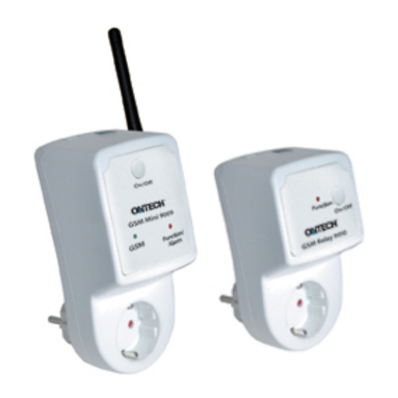
Ontech GSM Mini 9009
Ontech GSM Relay 9010
User Manual
Table of
Contents
Previous
Page
Next
Page
1
2
3
4
5
Advertisement
Table of Contents
Need help?
Do you have a question about the GSM Mini 9009 and is the answer not in the manual?
Ask a question
Questions and answers
This manual is also suitable for:
Gsm relay 9010
Table of Contents
Print
Rename the bookmark
Delete bookmark?
Delete from my manuals?
Login
Sign In
OR
Sign in with Facebook
Sign in with Google
Upload manual
Upload from disk
Upload from URL

Need help?
Do you have a question about the GSM Mini 9009 and is the answer not in the manual?
Questions and answers