Table of Contents
Advertisement
–
-
OFF
ON
SPEAKERS
PHONES
WARNING
: TO PREVENT FIRE OR SHOCK HAZARD,
DO NOT EXPOSE THIS APPLIANCE TO RAIN OR MOIS-
TURE.
IMPORTANT
The lightning flash with arrowhead symbol, within an
equilateral triangle, is intended to alert the user to the
presence of uninsulated "dangerous voltage" within the
product's enclosure that may be of sufficient magnitude
to constitute a risk of electric shock to persons.
IMPORTANT
FOR USE IN THE UNITED
KINGDOM
The wires in this mains lead are coloured in
accordance with the following code :
Blue
: Neutral
Brown
: Live
If the plug provided is unsuitable for your socket
outlets, the plug must be cut off and a suitable plug
fitted.
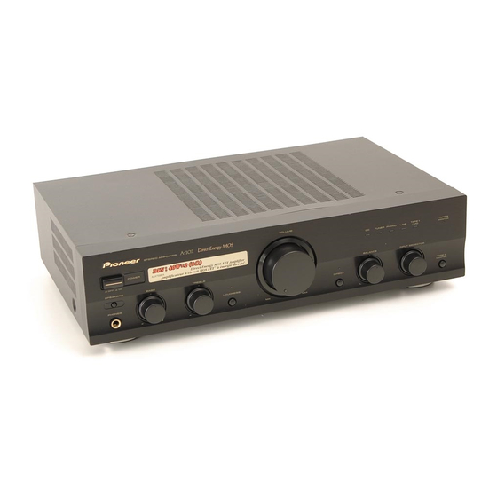
STEREO AMPLIFIER
z¿,?≥
z¿,?≥ Direct Energy MOS
STEREO AMPLIFIER
POWER
BASS
TREBLE
LOUDNESS
–
+
–
+
Thank you for buying this PIONEER product.
Please read through these operating instructions so you will know how to
operate your model properly. After you have finished reading the instructions,
put them away in a safe place for future reference.
In some countries or regions, the shape of the power plug and power outlet
may sometimes differ from that shown in the explanatory drawings. How-
ever, the method of connecting and operating the unit is the same.
RISK OF ELECTRIC SHOCK
CAUTION:
TO PREVENT THE RISK OF ELECTRIC SHOCK, DO NOT
REMOVE COVER (OR BACK). NO USER-SERVICEABLE
PARTS INSIDE. REFER SERVICING TO QUALIFIED
SERVICE PERSONNEL.
The cut-off plug should be disposed of and must not be
inserted into any 13 amp socket as this can result in electric
shock. The plug or adapter or the distribution panel should
be provided with a 5 amp fuse. As the colours of the wires
in the mains lead of this appliance may not correspond with
the coloured markings identifying the terminals in your plug,
proceed as follows :
The wire which is coloured blue must be connected to the
terminal which is marked with the letter N or coloured black.
The wire which is coloured brown must be connected
to the terminal which is marked with the letter L or coloured
red.
VOLUME
CD
BALANCE
DIRECT
L
MIN
MAX
This product complies with the Low Voltage Directive (73/
23/EEC), EMC Directives (89/336/EEC, 92/31/EEC) and CE
Marking Directive (93/68/EEC).
CAUTION
DO NOT OPEN
TAPE 1
TAPE 2
TUNER
PHONO
LINE
/MD
MONITOR
INPUT SELECTOR
TAPE 2
MONITOR
R
The exclamation point within an equilateral triangle is
intended to alert the user to the presence of important
operating and maintenance (servicing) instructions in the
literature accompanying the appliance.
Do not connect either wire to the earth terminal of a
three-pin plug.
NOTE
After replacing or changing a fuse, the fuse cover in the
plug must be replaced with a fuse cover which corre-
sponds to the colour of the insert in the base of the plug
or the word that is embossed on the base of the plug, and
the appliance must not be used without a fuse cover. If
lost, replacement fuse covers can be obtained from your
dealer.
Only 5 A fuses approved by B.S.I. or A.S.T.A to B.S.
1362 should be used.
1
<ARB7137>
Advertisement
Table of Contents

Related Manuals for Pioneer A-107


Summary of Contents for Pioneer A-107
- Page 1 MONITOR – – Thank you for buying this PIONEER product. Please read through these operating instructions so you will know how to operate your model properly. After you have finished reading the instructions, put them away in a safe place for future reference.
-
Page 2: Voltage Selector Switch
Check the power cord once in a while. When you find it damaged, ask your nearest PIONEER authorized service center or your dealer for a replacement. 220V... -
Page 3: Table Of Contents
PANEL FACILITIES ............. 6 FEATURES Direct Energy MOS Power Amp High-power Output of 40W+40W/8Ω(DIN) Pioneer introduces amp circuitry featuring HEX power MOS FET devices for high performance. Together with Wide-Range Linear Circuit Pioneer's original Wide Range Linear Circuit technology, This new current feedback circuit assures improved oper-... -
Page 4: Connections
CONNECTIONS Before making or changing the connections, switch off the power switch and disconnect the power cord from the AC outlet. Adaptor component Cassette deck/MD recorder Cassette deck CD player (graphic equalizer etc.) MINIDISC PLAY PLAY O U T The illustration shows U.K. and European models. SPEAKERS SIGNAL PHONO... -
Page 5: Connecting The Speaker Cords
CONNECTIONS CONNECTING THE SPEAKER CORDS CONNECTING THE INPUT/OUTPUT CORDS 1. Strip off the vinyl covering and twist the tip of the wire core. Connect the white plug to the L (left) channel, and the red plug 10mm to the R (right) channel. Be sure to push the plugs securely. Left channel Twist the wire core White plug... -
Page 6: Front Panel
PANEL FACILITIES [ FRONT PANEL ] VOLUME z¿,?≥ Direct Energy MOS STEREO AMPLIFIER TAPE 1 TAPE 2 TUNER PHONO LINE MONITOR POWER — SPEAKERS BASS TREBLE BALANCE INPUT SELECTOR PHONES LOUDNESS DIRECT TAPE 2 MONITOR – – POWER (—OFF/_ON) switch TAPE 2 MONITOR button/indicator Press to turn power to the unit ON and OFF. - Page 7 PANEL FACILITIES BALANCE control TREBLE tone control Should normally be left in the center position. Adjust balance Use to adjust the high-frequency tone. The center position is if the sound is louder from one of the speakers. If the right side the flat (normal) position.
-
Page 8: Rear Panel
PANEL FACILITIES [ REAR PANEL ] 2 3 4 7 8 9 VOLTAGE SELECTOR OUTLETS SPEAKERS SIGNAL PHONO TUNER LINE TAPE 1/MD TAPE 2 MONITOR 220V 240V 110V 120-127V AC INLET PLAY PLAY SWITCHED TOTAL 100 W MAX ª · ·... -
Page 9: Operations
OPERATIONS BEFORE BEGINNING OPERATIONS COPYING TAPES 1. Set the VOLUME control to minimum. When two decks are used, you can record the sounds from one deck onto the other. 2. Set the POWER switch to ON. 3. Press the SPEAKERS switch to ON. 4. - Page 10 OPERATIONS TO USE THE COMPONENT CONNECTED TO THE TAPE 2 MONITOR TERMINALS [For a cassette deck] ÷ A cassette deck connected here can be operated in the same way (recording and playback) as a deck connected to the TAPE 2 MONITOR terminals. ÷...
-
Page 11: Troubleshooting
Sometimes the trouble may lie in another component. Investigate the other components and electrical appliances being used. If the trouble cannot be rectified even after exercising the checks listed below, ask your nearest PIONEER authorized service center or your dealer to carry out repair work. -
Page 12: Specifications
PIONEER ELECTRONICS AUSTRALIA PTY. LTD. 178-184 Boundary Road, Braeside, Victoria 3195, Australia, TEL: [03] 9586-6300 PIONEER ELECTRONICS DE MEXICO S.A. DE C.V. San Lorenzo Num 1009 3er piso Desp. 302 Col. Del Valle, Mexico D.F. C.P. 03100 TEL: 5-688-52-90 <98L00ZF0P00>...
Need help?
Do you have a question about the A-107 and is the answer not in the manual?
Questions and answers