Table of Contents
Advertisement
Quick Links
Safety • Set-Up • Adjustments • Operation • Maintenance • Troubleshooting • Warranty • Parts Lists
OPERATOR'S MANUAL
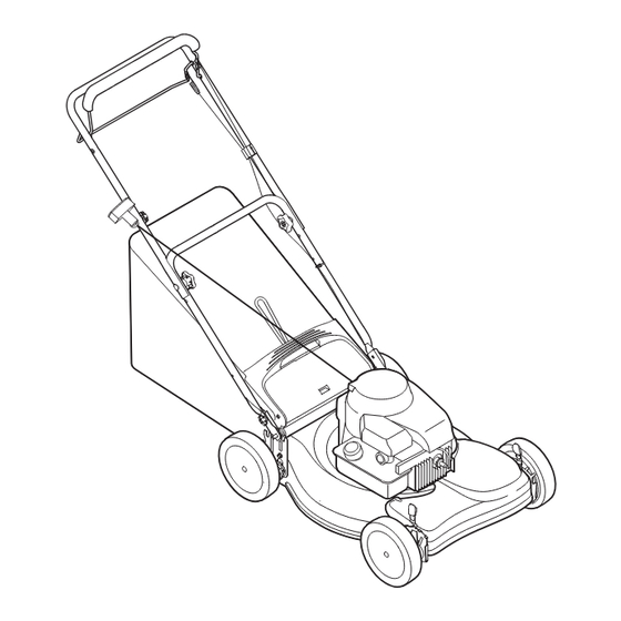
21" Self-Propelled Rotary Mower — Model Series 400
IMPORTANT:
READ SAFETY RULES AND INSTRUCTIONS
CAREFULLY BEFORE OPERATING EQUIPMENT.
PRINTED IN U.S.A.
MTD Products Ltd., P. O. Box 1386, KITCHENER, ONTARIO N2G 4J1
Model 460 shown.
769-02967A
11/7/07
Advertisement
Table of Contents

Related Manuals for MTD Pro 400 series


Summary of Contents for MTD Pro 400 series
- Page 1 Safety • Set-Up • Adjustments • Operation • Maintenance • Troubleshooting • Warranty • Parts Lists OPERATOR’S MANUAL Model 460 shown. 21” Self-Propelled Rotary Mower — Model Series 400 IMPORTANT: READ SAFETY RULES AND INSTRUCTIONS CAREFULLY BEFORE OPERATING EQUIPMENT. 769-02967A MTD Products Ltd., P.
-
Page 2: Table Of Contents
This Operator’s Manual is an important part of your new equipment. It will help you assemble, prepare and maintain the unit for best performance. Please read and understand what it says. Table of Contents Slope Gauge............3 Off-Season Storage .......... 11 Safe Operation Practices ........ -
Page 3: Slope Gauge
Use this page as a guide to determine slopes where you may not operate safely. Do not operate your lawn mower on such slopes. Slope Gauge WARNING Do not mow on inclines with a slope in excess of 15 degrees (a rise of approximately 2-1/2 feet every 10 feet). -
Page 4: Safe Operation Practices
WARNING: Engine Exhaust, some of its constituents, and certain vehicle components contain or emit chemicals known to the State of California to cause cancer and birth defects or other reproductive harm. DANGER: This machine was built to be operated according to the rules for safe operation in this manual. As with any type of power equipment, carelessness or error on the part of the operator can result in serious injury. - Page 5 8. Never fuel machine indoors because flammable vapors will accumulate in the area. 1. Mow across the face of slopes; never up and down. Exercise extreme caution when changing direction on 9. Never remove gas cap or add fuel while the engine is slopes.
-
Page 6: Set-Up & Adjustments
NOTE: This owner’s manual covers various models of lawnmowers. The units illustrated may vary slightly from your unit. Follow only those instructions which pertain to your model lawnmower. 1. Remove loose parts and any packing material which may be between upper and lower handles. Pull up and back on the upper handle to raise the handle into the operating position. - Page 7 6. To assemble the grasscatcher: a. Place bag over frame (black plastic side is the bottom of bag.) Insert the hooks on the frame through the holes in the side plastic channels of the bag. See Figure 3-6. b. Secure bag to frame by working the plastic chan- Setup and nels on bag over frame as shown in Figure 3-6.
-
Page 8: Operation
Know Your Lawn Mower Blade Control Handle Drive Control Handle Operating Choke Button (optional) Your Lawn Mower Recoil Starter Side Discharge (optional) WARNING Read, understand, and follow all instruc- tions and warnings Mulching Plug on the machine and Height Adjustment (optional) in this manual before Levers... - Page 9 WARNING: If you strike a foreign object, stop the engine. Remove wire from the spark plug, thor- oughly inspect the mower for any damage, and repair the damage before restarting and operating the mower. Extensive vibration Operating of the mower during operation is Your Lawn an indication of damage.
-
Page 10: Maintenance
Rear Flap Replacement The rear flap is attached to the back of the mower deck, and is designed to minimize the possibility that objects will be thrown from the rear of the mower toward the operator. If the rear flap becomes damaged, replace as follows. -
Page 11: Off-Season Storage
8. Tighten the hex bolt to the torque listed below: Blade Mounting Torque Center Bolt 450 in. lb. min., 600 in.lb. max. To insure safe operation of your unit, ALL nuts and bolts must be checked periodically for correct tightness. Belt Care Maintenance 1. -
Page 12: Trouble Shooting
Problem Cause Remedy 1. Blade control handle disengaged. 1. Engage blade control handle. Engine fails to start 2. Connect wire to spark plug. 2. Spark plug wire disconnected. 3. Fill tank with clean, fresh gasoline. 3. Fuel tank empty or stale fuel. 4. -
Page 13: Warranty
4 YEAR LIMITED WARRANTY For FOUR YEARS from the date of retail purchase within Canada, MTD PRODUCTS LIMITED will, at its option, repair or replace, for the original purchaser, free of charge, any part or parts found to be defective in material or workmanship. This warranty does not cover: Warranty 1. -
Page 14: Illustrated Parts Lists
MTD OHV Wheel Treads Zag Tread Bar Tread NOTE: Lawnmower features vary by model. NOT all parts listed on these pages are standard equipment. REMARQUE: Les caractéristiques des tondeuses varient selon le modèle. Les pièces énumérées dans ces pages ne font pas toutes partie de l’équipement de série. -
Page 15: Parts List
PART N° DE N° DE RÉF PIÈCE DE SCRIP TION DE SCRIP TION 747-1214 Drive Con trol Han dle Poignée de commande d’embrayage de l’entraînement 749-0928B Lower Han dle Guidon inférieure Parts List 710-0703 Carriage Bolt 1/4-10 x .75 Boulon ordi naire 1/4-20 x 0,75 618-04376A Trans mis sion Ass’y Trans mis sion... - Page 16 PART N° DE N° DE RÉF PIÈCE DE SCRIP TION DE SCRIP TION 747-0710 Hinge Pin Axe de charnière 687-02347 Front Bear ing Ass’y Roulement - avant 787-01277 21" Deck Ass’y (w/o side dis charge) Plateau de coupe de 21 po (sans éjection latérale) Parts List 787-01278 21"...
- Page 17 NOTES: For parts and/or accessories refer to customer support on page 2. Adressez-vous au «Service après-vente» à la page 2 pour ce qui concerne les pièces et/ou accessoires.
Need help?
Do you have a question about the 400 series and is the answer not in the manual?
Questions and answers