
Related Manuals for MTD Pro G1336


Summary of Contents for MTD Pro G1336
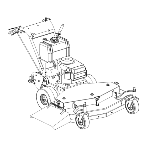
- Page 1 ® G1336 Walk-Behind Commercial Rotary Mowers Professional Turf Equipment OPERATOR’S AND SERVICE MANUAL...
-
Page 2: Table Of Contents
The list of safety precautions should receive particular attention. This manual presents the operating and maintenance instructions necessary to keep your MTD Pro mower at peak efficiency. If properly operated and maintained, your MTD Pro mower will give dependable and trouble-free service. -
Page 3: Safety Precautions
SAFETY PRECAUTIONS A. General: Watch for holes, sprinkler heads and other hidden hazards. Read this Operator’s Manual completely before starting the mower. Study the controls and learn the proper Reduce speed when making sharp turns. sequence of operation. Retain Operator’s Manual in a Always have proper footing on slopes and hill sides and safe place for future reference. -
Page 4: Safety Decals
SAFETY DECALS Keep safety decals clean. Replace any safety decal that is damaged, destroyed, missing, painted over or can no longer be read. Replacement safety decals are available through your dealer. (Left and right sides are determined standing behind the unit in the operating position.) WARNING OPEN BELT DRIVE STOP ENGINE BEFORE... - Page 5 SAFETY DECALS DANGER CAUTION To Avoid Injury: • Always connect the “ground” Serious bodily injury may result from failure (Black) cable last and remove it first whenever to follow safe operating procedures. performing any battery 1. Read the Operators Manual before maintenance.
-
Page 6: Specifications
SPECIFICATIONS POWER UNIT Engine: 13 HP Briggs. Type: 4-cycle, single-cylinder, recoil start. Air Cleaner: Dual element, dry-type. Lube System: Pressurized. Fuel Tank: 5 gallons, polyethylene. Transmission: 5 speeds forward and 1 speed reverse. Traction Drive: Double V-belts. Ground Speed: 2 to 4.5 MPH maximum. Drive Wheels: 13 x 6.50-6 pneumatic tires mounted on steel wheels with ball bearings. -
Page 7: Blade Clutch
OPERATING INSTRUCTIONS Releasing the operator presence levers with either the transmission shift lever in gear or the blade clutch engaged will shut off the engine. B. Initial Adjustments Disconnect the spark plug wire. Check the tire pressure. Drive Wheels should be inflated to 25 psi. - Page 8 OPERATING INSTRUCTIONS Move the mower outdoors. Check the engine gasoline Push the blade clutch lever forward until it engages and level. When filling the tank, stop when the gasoline the cutter blades start rotating. reaches one inch from the top. This space must be left Shift the transmission into first gear.
-
Page 9: Cutting Height Adjustment Table
CUTTING HEIGHT ADJUSTMENT TABLE Note: The front edge of the cutting deck should be 1/8” - 1/4” below the rear edge of the deck so that the blades are cutting grass in only the front half of their circular path. This decreases friction and reduces the drive power required. 1/4: Blade Spacers 1/2”... -
Page 10: D.lubrication Chart
MAINTENANCE D. LUBRICATION CHART: See Figures 3, 4 & 5 for Item Location NUMBER OF GREASING POSITIONS ITEM DESCRIPTION 32” & 36” 48” & 52” DAILY Cutter Blade Spindle Bearings Caster Wheel Bearing Caster Wheel Pivot Shafts Deck Idler Pulley Pivot Arms EVERY Drive Wheel Bearings HOURS... -
Page 11: To Change The Transmission Drive Belt
MAINTENANCE Figure 6 Figure 7 d. Slip the long blade drive belt off of the pulleys. e. (48" ONLY) Loosen the idler pull rod which holds the idler pulley tight against the short blade drive belt. (Item K, Figure 8.) f. -
Page 12: To Change A Spindle Assembly
MAINTENANCE dowel on top of the spindle and tap it with a hammer to drive the spindle out of the bearings and the spindle housing. c. Pull the seal spacer out of the top seal. d. Using a large screwdriver, pry the seals out of each end of the spindle housing. -
Page 13: Replacement Parts - Spindle
8. TO ADJUST THE LITE-TOUCH (MANUALLY) a.rThree holes in the belt guard allow you to reposition the hex cap screw to adjust the brake lever. The top hole (lite tension), the middle hole (medium tension) and the lower hole (hard tension). -
Page 14: Maintenance Record
MAINTENANCE SUGGESTED MOWER REPLACEMENT PARTS PART # Description 36" 00050125 Rotary Blade, 18" 01007591 Blade Bolt 00011807 Blade Nut 00021924 Blade Spacer 01007577 Blade Spacer 00050441 Drive Belt 01000194 Transmission Drive Belt 01000151 Traction Drive Belt SUGGESTED ENGINE REPLACEMENT PARTS Engine Air Filter (Primary) Air Filter (Safety) - Page 15 Supplement Parking Instructions All Gear Walk-Behind Mowers INCORRECT Instructions 1. When parking mower on a hill, position mower perpendicular to slope. PARK MOWER FACING DOWN SLOPE. 2. Turn off the engine. 3. Place the Transmission Shift Lever in First Gear. 4.
-
Page 16: Warranty
1. What Is Covered By This Warranty. This limited warranty covers any defect in materials or workmanship in your MTD Pro equipment for two year from the date of purchase for the first user purchaser. MTD Pro will replace or repair any part or parts without charge through your authorized MTD Pro dealer.
Need help?
Do you have a question about the G1336 and is the answer not in the manual?
Questions and answers