Table of Contents
Advertisement
Advertisement
Table of Contents

Related Manuals for Nidek Medical NT-510

Summary of Contents for Nidek Medical NT-510
- Page 1 NON CONTACT TONOMETER Model OPERATOR’S MANUAL...
- Page 2 NIDEK CO., LTD. : 34-14, Maehama, Hiroishi-cho, Gamagori, Aichi 443-0038, Japan (Manufacturer) Telephone: 81-533-67-6611 Facsimile: 81-533-67-6610 NIDEK CO., LTD : 3F Sumitomo Fudosan Hongo Bldg., 3-22-5, Hongo, (Tokyo Office) Bunkyo-Ku, Tokyo 113-0033, Japan Telephone: 81-3-5844-2641 Facsimile: 81-3-5844-2642 NIDEK INCORPORATED : 47651 Westinghouse Drive, Fremont, California 94539, U. S. A. (United States Agent) Telephone: 1-510-226-5700 Facsimile: 1-510-226-5750...
-
Page 3: Safety Precautions
BEFORE USE, READ THIS MANUAL. This operator’s manual contains information necessary for the operation of the NIDEK NON CONTACT TONOMETER Model NT-510. This manual includes the operating procedures, safety precautions, and specifications. This manual is necessary for proper use. Especially, the safety precautions and operating procedures must be thoroughly understood prior to operation of the device. - Page 4 Use precautions Before Use • Do not use the device for other than the intended purpose. CAUTION NIDEK is not responsible for accidents or malfunctions caused by misuse. • Be sure to read the manual prior to operation of the device to understand the safety precautions and operating procedures thoroughly.
- Page 5 The NT-510 complies with these requirements as tabled on pages 79 to 82. Follow the guidance in the tables for use of the device in an electromagnetic...
- Page 6 During Use • Before starting measurement, set the safety stopper for each patient to prevent the air WARNING nozzle from touching the patient’s eye. Contact between the air nozzle and the eye may damage the cornea. • Before use, perform visual and operation checks. If abnormal conditions are CAUTION encountered, stop using the device.
- Page 7 • In the event of smoke or strange odors, immediately turn off the device and CAUTION disconnect the power plug from the outlet. After you are sure that the smoke has stopped, then contact NIDEK or your authorized distributor. Usage of the device under such abnormal conditions may cause fire or electric shock. In case of fire, use a dry chemical (ABC) extinguisher to extinguish the fire.
- Page 8 • Never use portable or mobile radio frequency (RF) devices in the vicinity of this CAUTION device. These devices may adversely affect medical electrical equipment and malfunction may result. • When connecting the device to the PC* that is not corresponded to IEC60601-1, be sure to supply power through the isolation transformer.
- Page 9 After Use • When the device is not in use, turn off the power switch and put the dust cover over CAUTION the device. If not, dust may affect the measurement accuracy. • Do not yank the power cord to disconnect it from a wall outlet but hold the plug. This can damage the metal core of the cord and may result in fire, short circuit or elec- tric shock.
- Page 10 Maintenance • Only NIDEK service representatives or hospital personnel trained by NIDEK should CAUTION attempt to modify or touch the inside of the device and/or upgrade the software. NIDEK is not responsible for any accidents resulted from improper servicing. • When performing maintenance work, secure sufficient maintenance space. Maintenance work in an insufficient space may result in injury.
- Page 11 { Patient environment The patient environment represents a space where there is a possibility of direct contact between the patient or the operator and third person. When another type of device is used in the patient environment, use a device that complies with IEC 60601-1.
-
Page 13: Table Of Contents
Table of Contents 1. BEFORE USE ........1 1.1 Outline of device . - Page 14 3. OPERATION WHEN PERIPHERAL DEVICES ARE CONNECTED ........57 3.1 Connecting to Computer .
-
Page 15: Before Use
BEFORE USE Outline of device NON CONTACT TONOMETER Model NT-510 is designed to non-contact tonometry measurement. The non-contact tonometry function measures the intraocular pressure without contacting the eye. Tonometry is performed for the early detection of glaucoma, and for preoperative examination and postoperative care in ophthalmology. -
Page 16: Indications For Use
BEFORE USE Indications for Use Indications for Use The NON CONTACT TONOMETER NT-510 is a medical apparatus which performs measurement of intraocular pressure. -
Page 17: Principles
BEFORE USE Principles Principles Based on the Imbert-Fick principle (W = Pt × A), the intraocular pressure is calculated by dividing the amount of air pressure into the area of applanated surface. The device increases the air pressure puffed onto the cornea in proportion to time. The shape of the cornea changes gradually in the order of convex surface applanated surface concave surface. -
Page 18: Device Description
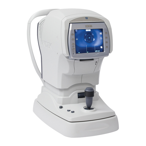
BEFORE USE Device Description Device Description { Front view Function buttons LCD screen Memory indicator Start button Joystick Locking lever Power button Cover open button Printer cover Function buttons Used to set the device and to switch the screen. Functions assigned to the function buttons are displayed by icon next to each switch on the screen. Lower two buttons on the left of the screen have unique functions when the measurement screen is displayed. - Page 19 BEFORE USE Device Description •CLR button ( Used to clear the measured data. When the CLR button is pressed for about a second, all the measured data is erased. •Print button ( When this button is pressed while the memory indicator is lit, measured results are printed out. If this button is pressed when the memory indicator is turned off, the printer paper is fed.
- Page 20 BEFORE USE Device Description { Rear view Eyelid detection LEDs Eye level marker Forehead rest LED for Corneal Illumination Chinrest up/down buttons Air nozzle Safety stopper Chinrest Patient sensor Forehead rest During measurements, the patient’s forehead should be gently placed over the forehead rest. Clean the forehead rest for each patient.
- Page 21 BEFORE USE Device Description Safety stopper Used to provide a safety space so that the air nozzle does not touch the patient’s eye. Change the position of the stopper for each patient to keep the proper amount of the space for safety. While pressing the safety stopper, “RTN TO ORG”...
- Page 22 USB-A connector The followings are possible with USB connection. • Barcode or magnetic card reader can be connected to read the patient's ID to the NT-510. • USB flash drive can be connected to upgrade the software of the NT-510.
-
Page 23: Measurement Screen Description
Auto-tracking mark This mark indicates that the auto-tracking (alignment in the direction) is turned on. up-and-down NT-510 displays or Manual (No indication). Auto-tracking in the up-and-down directions is turned on. (No indication) Manually align the device and bring the eye into focus. - Page 24 BEFORE USE Measurement Screen Description Auto-shooting mark Indicates the setting of the auto-shooting function. Measurement starts automatically when the eye is best aligned and focused. (No indication) Press the start button to start measurement. Applanation area ( Represents the range in which air is puffed to the cornea. Charge indicator Indicates that the device is in standby mode for puffing air.
- Page 25 BEFORE USE Measurement Screen Description ID indication Displays the patient's ID read from the barcode or magnetic card reader. <When Page 2 is displayed> Parameter button ( Switches the screen to the PARAMETER SETTING screen. Pressing the button for about a second switches the screen to the PARAMETER SETTING screen.
-
Page 26: Labels And Indications On Device
BEFORE USE Labels and Indications on Device Labels and Indications on Device To call the operator’s attention, the device is provided with labels and indications. If labels are curling up or characters are faded and become barely legible, contact NIDEK or your authorized distributor. -
Page 27: Checking Contents
BEFORE USE Checking Contents [Underside view] See “ Before Use” (page II) and “3 OPERATION WHEN PERIPHERAL DEVICES ARE CONNECTED” (page 65). Checking Contents Unpack the contents from the shipping carton and check them. The following are included in the standard configuration. •... -
Page 28: Before First Use
BEFORE USE Before First Use Before First Use Place the device on a stable table and connect a power cord to it. • Be sure not to install the device in a location exposed to the direct sunlight or a place directly under bright lights. - Page 29 BEFORE USE Before First Use • The electrical outlet must have a grounding terminal. CAUTION Electric shock or fire may occur in the event of device malfunction or power leakage. Turn the power switch on ( The initial screen is displayed on the LCD dis- play and the device starts initializing.
- Page 30 BEFORE USE Before First Use { Please see here when you want to do like this. When Refer to the following. You need to know the details of the “PRESSURE “2.3.1 Measuring puffed air pressure check during CHECK MODE” message displayed at device start-up. startup”...
-
Page 31: Operating Procedures
OPERATING PROCEDURES Operation Flow Turning ON the device "2.2 Preparation for Measurement (Page 18)" Turn on the device and configure it us as necessary. Set up the patient. Measurement "2.3 Measurement (Page 24)" Printout "2.6 Printing (Page 37)" * For transferring data to connected devices: 3 OPERATION WHEN PERIPHERAL DEVICES ARE CONNECTED Turning OFF the device "2.4 Completion of Measurements (Page 33)"... -
Page 32: Preparation For Measurement
OPERATING PROCEDURES Preparation for Measurement Preparation for Measurement Turn the power switch on ( Power switch The title screen is displayed and the device is ini- tialized. Initial screen Wait for a while until the screen switches to the measurement screen. •... - Page 33 OPERATING PROCEDURES Preparation for Measurement The measurement screen is displayed. Measurement screen • “NO PAPER” is displayed on the screen if the power switch is turned on with no printer paper loaded. Load the printer paper. Perform checks before use. Perform the following checks before use.
- Page 34 OPERATING PROCEDURES Preparation for Measurement Establish the measurement conditions. The following conditions should be specified: 1 : Measurement mode: Auto-tracking, Auto-shooting, Target type •Setting of the Auto-tracking and Auto-shooting Specify the alignment (up-and-down) and the method of triggering measurements. Specify the methods while holding down the auto button auto- On-screen Auto-tracking...
- Page 35 OPERATING PROCEDURES Preparation for Measurement Press the RNG button to select the mea- surement range. Every time the button is pressed, the measure- ment range switches in the following order: “APC 40” o “APC 60” o “40” o “60” o “APC 40” o ….
- Page 36 OPERATING PROCEDURES Preparation for Measurement 2) Instruct the patient to take off spectacles or contact lenses and sit on a chair. 3) Have the patient place his/her chin on the chinrest as deeply as possible, and his/her forehead on the forehead rest lightly. 4) Adjust the height of the chinrest by the chin- Eye level marker rest up/down button (...
- Page 37 OPERATING PROCEDURES Preparation for Measurement Set the safety space between the patient’s eye and air nozzle with the safety stop- per. • Before the measurement, be sure to set the safety stopper. WARNING The air nozzle may touch and scratch the cornea. 1) Pressing the safety stopper ,operate the joystick so that the air nozzle approaches the cornea slowly.
-
Page 38: Measurement
OPERATING PROCEDURES Measurement Measurement Manipulate the joystick to display the patient’s eye on the screen. By tilting the joystick to the right and left, the main body moves right, left, back and forth. By turning the upper part of the joystick, the measuring unit moves up and down. - Page 39 OPERATING PROCEDURES Measurement Perform alignment and focusing. The methods of alignment and focusing vary Focusing indicator according to the 22. TRACKING SW parameter setting * For details of the setting, see "• Setting of the Auto-track- ing and Auto-shooting (Page 20)" Align the alignment spot reflected over the patient’s eye with the target ( Perform focusing according to the indication of...
- Page 40 OPERATING PROCEDURES Measurement When the auto-tracking function is turned off: 1) Manipulate the joystick to move the align- Up-and-down and side-to-side align- ment spot reflected by the patient’s eye ment: Manual within the alignment target. 2) As the focusing indicator is displayed, manipulate the joystick until the optimal focusing indicator is displayed.
- Page 41 OPERATING PROCEDURES Measurement Indication of the focusing indicator: Push the joystick forward and pull it backward until the focusing indicator shows the optimal state. NT old type RKT type Too close to the patient’s eye Pull the joystick backward to move the main body away from the patient’s eye.
- Page 42 OPERATING PROCEDURES Measurement <Error messages during the measurement> Error message Description Alignment is not proper. (Alignment error) Perform the alignment and the measurement again. As the eye was not opened enough, corneal applanation was insufficient. Instruct the patient to open his or her eyes wider. (Applanation error) If the patient cannot do so, ask an assistant to open the eyelids wider by using a swab, etc.
- Page 43 OPERATING PROCEDURES Measurement { If the “CHECK THE EYE” error occurs: Check the condition of the patient’s eye. If the patient cannot open the eye wide or eyelashes are over the applanation area, you have to help the patient open the eye wide. For a watery eye, have the patient blink his or her eyes, or wipe the tears.
- Page 44 OPERATING PROCEDURES Measurement Measurement completes. End measurement by manipulating the joystick backward because measurement is performed repeatedly regardless of the set times. Pull the joystick backward once and move the main body to the other eye. The measured eye indicator of the other eye blinks.
-
Page 45: Measuring Puffed Air Pressure Check During Startup
OPERATING PROCEDURES Measurement 2.3.1 Measuring puffed air pressure check during startup It is possible to parameter-set whether or not to check the pressure of puffed air before mea- surements. Checking contents at the device start-up are different according to the parameter setting. Parameter name Description Selection of whether or not to automatically check the air pressure... - Page 46 OPERATING PROCEDURES Measurement 3) The test of the puffed air of 60 mmHg is per- formed in the same way. Confirm the check result. If the “PRESSURE PEAK ERROR” message is displayed, the “PRESSURE PEAK ERROR (60)” message is printed out after the completion of the check.
-
Page 47: Completion Of Measurements
OPERATING PROCEDURES Completion of Measurements Completion of Measurements 2.4.1 Normal shutoff Turn off ( ) the power switch. It is allowed to turn off the power with any screen displayed. To exit measurements, inspect the air nozzle etc. for soiling and clean them. See "4.5 Cleaning (Page 77)". -
Page 48: Shutoff Before Transporting The Device
OPERATING PROCEDURES Completion of Measurements 2.4.2 Shutoff before transporting the device Before the device is transported, put the device in packing mode. In packing mode, the measuring unit and chinrest are automatically set in preparation for transportation. Inspect the air nozzle etc. for soiling and clean them. See "4.5 Cleaning (Page 77)". -
Page 49: Selecting Mode
OPERATING PROCEDURES Selecting Mode Selecting Mode 2.5.1 Sleep mode The device goes into sleep mode automatically to save power if no button have been pressed for a certain period of time. The time that the device goes into sleep mode can be selected from 5 minutes, 10 minutes, 15 minutes, or NO (no sleep mode) with the 23. -
Page 50: Eyelid Detection Mode
OPERATING PROCEDURES Selecting Mode 2.5.2 Eyelid detection mode With this mode, the device always checks the eye for the amount of eye-opening and the measure- ment takes place automatically only when the eyelid is opened wide. { Activating and cancelling eyelid detection mode Press the eyelid detection mode button to activate or cancel the mode. -
Page 51: Printing
OPERATING PROCEDURES Printing Printing 2.6.1 Printing measured data Measured data is printed out by pressing the print button after measurement. Printing completes with paper still attached so that it does not fall. Tear off the paper to detach. • When the 11. PRINT parameter is set to AUTO, printing starts automatically when the measurements of both eyes complete. -
Page 52: Printing Parameter Settings
OPERATING PROCEDURES Printing 2.6.2 Printing parameter settings The present parameter settings, set time, comments and maintenance program versions are printed out. Press the parameter button for about a second. The PARAMETER SETTING screen is displayed. The parameter No. and parameter names are displayed. -
Page 53: Parameter Settings
OPERATING PROCEDURES Parameter Settings Parameter Settings NT-510 is provided with parameters that set various functions according to the user’s usage pattern. The procedure for checking and changing the parameter settings is explained. Press the parameter button for about a second The PARAMETER SETTING screen is displayed and parameter items are displayed. - Page 54 OPERATING PROCEDURES Parameter Settings Press the execute button to switch to the [PRINT1] screen etc. Parameters and their settings are displayed. A parameter that is being selected is highlighted. PRINT1 screen Press the up/down button to select a parame- ter to be changed Move the highlight.
- Page 55 OPERATING PROCEDURES Parameter Settings To change the page of parameter: Page up button Displays the previous page. Page down button Displays the next page. Repeat Steps 4 to 5 to change the desired parameter settings. To finish setting the parameters, press the exit button The screen returns to the step1 PARAMETER SETTING screen To finish setting the parameters, press the exit button...
-
Page 56: Parameter Tables
OPERATING PROCEDURES Parameter Settings 2.7.1 Parameter tables NT (NT measurement)] * Underlined options indicate factory settings. Parameter Settings SET LOW CONF YES / NO LOW CONF LV. YES / NO LOW CONF ALARM YES / NO FIX LED BLINK YES / NO NT CONTINUE 3 - 10 (Factory setting: 3) DECIMAL DIGIT... - Page 57 OPERATING PROCEDURES Parameter Settings [PRINT1 (Print setting 1)] * Underlined options indicate factory settings. Parameter Settings PRINT MANUAL / AUTO / NO ECONO. PRINT YES / NO PRINT&CLEAR YES / NO PRINT DENCITY LOW / MIDDLE / HIGH PATIENT NO. YES / NO SET PATIENT NO.
- Page 58 OPERATING PROCEDURES Parameter Settings 18 : DATE FORMAT (date format) Selects the format of date Y/M/D Year, Month, Date M/D/Y Month, Date, Year D/M/Y Date, Month, Year No printing 19 : PRINT COMMENT Selects whether or not to print comments. 20 : NT PRINT (NT print format) Printout format in measurement Prints the NT measured data vertically.
- Page 59 OPERATING PROCEDURES Parameter Settings [FUNCTION 1 (Various functions 1)] * Underlined options indicate factory settings. Parameter Settings PRESSURE CHECK YES / NO / DAY TRACKING SW TRC/ASHOT / ASHOT ON / ASHOT OFF SLEEP 5MIN / 10MIN / 15MIN / NO BEEP LOW / HIGH / NO NT BRIGHTNESS...
- Page 60 NCP10 NCP10-compliant device 32 : I/F FORMAT (communication format) Selects the format of data to be transmitted.For the NT-510, I/F FORMAT is fixed to ALL. All data are transferred. 33 : BAUD-RATE Selects the baud-rate (bit transmission speed) for communication.
- Page 61 OPERATING PROCEDURES Parameter Settings 35 : CR CODE (line feed code) Selects whether or not to attach CR (carriage return) code at the end of data to be transmitted. [READER (Barcode/magnetic card reader function)] * Underlined options indicate factory settings. Parameter Settings READER START...
-
Page 62: Setting Network Function
1. DHCP can be set to on. 2. TCP/IP: IP address and subnet mask of the NT-510 3. File sharing of the computer: User name, password, and domain 4. Folder setting and name in the computer in which the measured data is to be saved •... - Page 63 * When the TEST button on the lower left in the NETWORK screen is pressed, whether or not the LAN interface cable is connected to the NT-510 is checked. A message is dis- played for two seconds with a beep sound.
- Page 64 OPERATING PROCEDURES Parameter Settings 53 : IP Input the IP address. The input procedure is as follows. Press to select "53. IP". The screen is as shown to the right. Press the execute button The screen changes to the IP address input screen.
- Page 65 OPERATING PROCEDURES Parameter Settings 54 : MASK Input subnet mask. The input procedure is same as "53. IP". Refer to above "53. IP". * When "52. DHCP" is set to YES, subnet mask is displayed as "0. 0. 0. 0" and cannot be selected. 55 : USER Input the user name of the connected computer.
- Page 66 OPERATING PROCEDURES Parameter Settings 5) Press the execute button or start button to set YES or NO. The screen returns to Step 1) screen. In the screen, input IP address is displayed. When returning to the user name input screen, press 56 : PASSWORD Input the login password for the user name of the connected computer.
-
Page 67: Setting Date And Time
OPERATING PROCEDURES Parameter Settings 2.7.3 Setting date and time When the date and time of the printout is not correct, set the correct date and time. • If the device is not turned on for three weeks, the date and time may be shifted. Press the parameter button for about a second... - Page 68 OPERATING PROCEDURES Parameter Settings Press the up button or down button move the highlight to an item to be changed. Press the right button or the left button to change the setting. Increases the number. Right button Decreases the number. Left button To change the time format: Change the time format between the 24-hour and 12-hour.
-
Page 69: Entering Comments
OPERATING PROCEDURES Parameter Settings 2.7.4 Entering comments Comments to be printed can be changed (factory setting: “NIDEK NT-510”). Press the parameter button for about a second. The PARAMETER SETTING screen is dis- played. Press the down button to select the COM- MENT SET parameter. - Page 70 Press the exit button to return to the measurement screen. The entered comments are saved. • When the start button is held down with the SET COMMENT screen displayed, comments return to the default setting (“NIDEK NT-510”).
-
Page 71: Operation When Peripheral Devices Are Connected
The NT-510 exports measured data by connecting to an external device such as computer. The NT-510 also reads patient's ID data by a USB-connected barcode or magnetic card reader. • Before connecting cables to devices, turn the devices off and disconnect the power CAUTION cord from an outlet. -
Page 72: Rs-232C Connection
) on the bottom of the NT-510 via an interface cable (optional). Connect the cable with the device laid down. Attach a ferrite core (optional) to the interface cable connector of the NT-510. Ferrite core (optional) RS-232C cable (optional) To computer... -
Page 73: Network Connection (Lan)
Network connection (LAN) { Connecting procedure Connect a computer to the LAN port on the bottom of the NT-510 via a LAN cable. Connect the cable with the device laid down. Attach a ferrite core (optional) to the interface cable connector of the NT-510. -
Page 74: Connecting Barcode / Magnetic Card Reader
3.2.1 Outline By connecting the optional barcode reader or magnetic card reader to the NT-510 via USB, the patient ID can be read to the NT-510. • The patient ID can be read before and after measurement but must be performed it before printing. -
Page 75: Maintenance
MAINTENANCE Troubleshooting In the event that the device does not work correctly, correct the problem according to the following table before contacting NIDEK or your authorized distributor. Symptom Remedy • The power cord may not be correctly connected. The LCD display does not turn on. Reconnect it securely. - Page 76 MAINTENANCE Troubleshooting Symptom Remedy • The auto-tracking function or auto-shooting function may not have been turned on. Turn them on with the auto button • Room illumination may be reflecting on the cornea. Change the location and try measurement again. •...
-
Page 77: Error Messages And Countermeasures
MAINTENANCE Error Messages and Countermeasures Error Messages and Countermeasures If one of the following error codes is displayed on the screen or printed out, follow the suggestions in the cause and countermeasure column. The error code, detailed indications and serial number of your device are helpful in proper servicing. Error code Cause and countermeasure •... - Page 78 Equipment other than USB flash drive and barcode / magnetic card reader is connected to USB- ERR601 A port and started. • Remove the connected equipment then restart the NT-510. • Error related to a connecting device USB flash drive or barcode / magnetic card reader connected to USB-A port was not ERR602 recognized.
- Page 79 MAINTENANCE Error Messages and Countermeasures Error code Cause and countermeasure • Error related to log on. ERR756 Logging on to the PC is not allowed. (The user name or password is incorrect.) • Check the user name and password and input correctly. •...
-
Page 80: Replacing Printer Paper
MAINTENANCE Replacing Printer Paper Replacing Printer Paper When a red line appears on the side of printer paper, it means that paper is running short. In such a case, stop using the printer and replace printer paper with new one. •... - Page 81 MAINTENANCE Replacing Printer Paper Insert new printer paper. Load printer paper as shown in the picture on the right. Set printer paper so that its end is exposed from the cover. • If the roll is loaded in such a way that paper becomes upside down, it is not possible to print data out.
-
Page 82: Fixing Chinrest Paper
MAINTENANCE Fixing Chinrest Paper Fixing Chinrest Paper Disconnect the two fixing pins from the chinrest. Remove a proper number of chinrest papers from the pack. It is impossible to fix the whole pack of chinrest paper. Be sure to fix a stack with a thickness of 6 mm of less. -
Page 83: Cleaning
MAINTENANCE Cleaning Cleaning When the cover or panel of the device becomes dirty, wipe with a soft cloth. For stubborn dirt, immerse the cloth in a neutral detergent, wring well, and wipe. Finally wipe with a dry and soft cloth. •... -
Page 84: Cleaning Printer
MAINTENANCE Cleaning Gently wipe the glass part with a cotton swab dampened with methanol or abso- lute alcohol. • Gently wipe the air nozzle without rubbing or without wiping it with foreign particles settled. CAUTION The glass part may be scratched. Check the glass part for soiling again. -
Page 85: List Of Replacement Parts
MAINTENANCE List of Replacement Parts List of Replacement Parts Part name Part number Note Printer paper 80620-00001 Width 58 mm, Length 25 m Chinrest paper 32903-M047 Pack of chinrest paper After replacing consumables, restock them. - Page 86 MAINTENANCE List of Replacement Parts...
-
Page 87: Specifications And Accessories
[Degree of safety in the presence of a flammable anesthetic mixture with air, or a flammable anesthetic mixture with oxygen or nitrous oxide] The NT-510 is classified as a device not suitable to be used in the presence of a flammable anesthetic mixture with air, or a flammable anesthetic mixture with oxygen or nitrous oxide caused by leakage or a discharge. -
Page 88: Safety Features
To ensure safe use, the device is provided with the following safety features. <Patient sensor> Verifies that no patient is in front of the NT-510 when checking the puffed air. When the sensor detects the patient, the puffed air check is not performed. -
Page 89: Specifications
SPECIFICATIONS AND ACCESSORIES Specifications Specifications { Measurement of intraocular pressure • Measurable range 1 to 60 mmHg • Intraocular pressure measurement value Less than 1mmHg: Displayed as 1mmHg 1 to 60mmHg: Measurement value in 1mmHg integers Average value: Measurement value in units of 0.1mmHg 60mmHg or higher: OVR display •... - Page 90 SPECIFICATIONS AND ACCESSORIES Specifications { Environmental conditions (during use) • Temperature 10 to 35qC (50 to95qF) • Humidity 30 to 90% (No condensation) • Atmospheric pressure 800 to 1060 hPa • Other No dust nor smoke { Environmental conditions (during transport and storage) •...
-
Page 91: Standard Configuration
SPECIFICATIONS AND ACCESSORIES Standard Configuration Standard Configuration 5.4.1 Standard accessories • Printer paper 3 rolls • Power cord 1 unit • Dust cover 1 unit • Fixing pins for chinrest paper 2 units • Pack of chinrest paper 1 unit •... - Page 92 SPECIFICATIONS AND ACCESSORIES Standard Configuration...
-
Page 93: Emc (Electromagnetic Compatibility)
EMC (IEC 60601-1-2:2001+A1:2004) Guidance and manufacture's declaration - electromagnetic emissions The NT-510 is intended for use in the electromagnetic environment specified below. The customer or the user of the NT-510 should assure that it is used in such an environment. - Page 94 220V, this standard is not applicable. The NT-510 is intended for us e in the electrom agnetic environm ent s pecified below. The cus tom er or the us er of the NT-510 s hould as s ure that it is us ed in s uch an environm ent.
- Page 95 EMC (ELECTROMAGNETIC COMPATIBILITY) Guidance and manufacturer's declaration - electromagnetic immunity The NT-510 is intended for use in the electromagnetic specified below. The customer or the user of the NT- 510 should assure that it is used in such an environment.
- Page 96 Rec om m ended s eparation dis tanc es between portable and m obile RF c om m unic ations equipm ent and the NT-510 Th e N T-5 1 0 in in te n d e d fo r u s e in a n e le ctro m a g n e tic e n viro n m e n t in w h ich ra d ia te d R F d is tu rb a n ce s a re co n tro lle d .
-
Page 97: Glossary
GLOSSARY zAPC (Automatic Puff Control) The function which performs the normal measurement initially, however, in subsequent measurements, automatically reduces the air pressure in order to measure using more gen- tle puff of air. zApplanation To flatten the cornea by pressing it with air pressure. zSafety space The space maintained by the safety stopper so that the tip of the air nozzle does not touch the cornea. - Page 98 GLOSSARY zFocusing indicator The indicator which shows the distance between the corneal center of the patient’s eye and the tip of the air nozzle. For the NT measurement, there are two display types. zEyelid detection mode In this mode, eyes are constantly checked for the condition of opening. NT measurement takes place only when the eye is opened wide enough.
-
Page 99: Index
INDEX Air nozzle ....... . 6 LAN connector ....... . 8 Applanation area . - Page 100 INDEX...
Need help?
Do you have a question about the NT-510 and is the answer not in the manual?
Questions and answers