Advertisement
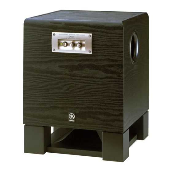
YST-SW320
IMPORTANT NOTICE
This manual has been provided for the use of authorized YAMAHA
Retailers and their service personnel.
It has been assumed that basic service procedures inherent to the industry,
and more specifically YAMAHA Products, are already known and
understood by the users, and have therefore not been restated.
WARNING:
Failure to follow appropriate service and safety
procedures when servicing this product may result in
personal injury, destruction of expensive components,
and failure of the product to perform as specified. For
these reasons, we advise all YAMAHA product owners
that any service required should be performed by an
authorized YAMAHA Retailer or the appointed service
representative.
IMPORTANT:
The presentation or sale of this manual to any individual
or firm does not constitute authorization, certification
or
recognition
capabilities, or establish a principle-agent relationship
of any form.
The data provided is believed to be accurate and applicable to the unit(s)
indicated on the cover. The research, engineering, and service departments
of YAMAHA are continually striving to improve YAMAHA products.
Modifications are, therefore, inevitable and specifications are subject to
change without notice or obligation to retrofit. Should any discrepancy
appear to exist, please contact the distributor's Service Division.
WARNING:
Static discharges can destroy expensive components.
Discharge any static electricity your body may have
accumulated by grounding yourself to the ground buss
in the unit (heavy gauge black wires connect to this
buss).
IMPORTANT:
Turn the unit OFF during disassembly and part
replacement. Recheck all work before you apply power
to the unit.
1 0 0 7 2 0
SUBWOOFER SYSTEM
of
any
applicable
technical
SERVICE MANUAL
SERVICE MANUAL
CONTENTS
TO SERVICE PERSONNEL . . . . . . . . . . . . . . . . . . . . 1
SPECIFICATIONS . . . . . . . . . . . . . . . . . . . . . . . . . . . . 1
REAR PANEL . . . . . . . . . . . . . . . . . . . . . . . . . . . . . . . 2
DISASSEMBLY PROCEDURES . . . . . . . . . . . . . . . 3-4
ADJUSTMENTS . . . . . . . . . . . . . . . . . . . . . . . . . . . . 5-6
PRINTED CIRCUIT BOARD . . . . . . . . . . . . . . . . . 7-12
BLOCK DIAGRAM . . . . . . . . . . . . . . . . . . . . . . . . . . . 13
SCHEMATIC DIAGRAM . . . . . . . . . . . . . . . . . . . . . . 14
PARTS LIST . . . . . . . . . . . . . . . . . . . . . . . . . . . . . 15-22
YST-SW320
Advertisement
Table of Contents

Related Manuals for Yamaha YST-SW320


Summary of Contents for Yamaha YST-SW320
-
Page 1: Table Of Contents
SERVICE MANUAL SERVICE MANUAL IMPORTANT NOTICE This manual has been provided for the use of authorized YAMAHA Retailers and their service personnel. It has been assumed that basic service procedures inherent to the industry, and more specifically YAMAHA Products, are already known and understood by the users, and have therefore not been restated. -
Page 2: To Service Personnel
SPECIFICATIONS Type ..Advanced Yamaha Active Servo Technology Driver ... 25 cm (9-13/16") cone woofer (JA25600) Magnetically shielded type Amplifier Output . -
Page 3: Rear Panel
YST-SW320 REAR PANEL R, T models only U, C models A model B, G models R model T model... -
Page 4: Disassembly Procedures
YST-SW320 DISASSEMBLY PROCEDURES (Remove parts in the order as numbered.) 1. Removal of Front Panel Ass'y 3. Removal of Rear Panel Ass'y Remove 4 screws ( q ) and then remove the Front Remove 12 screws ( r ) in Fig. 3. - Page 5 YST-SW320 Installation of power switch Rapid cures bond (such as 5 minute epoxy) is required to fix the power switch. As shown in Fig. A, apply rapid cures bond (such as 5 minute epoxy) to the power switch (the area which contacts the rear panel), insert it in the rear panel and make sure it is fixed.
-
Page 6: Adjustments
Setting 1) Set the signal generator to the sine wave, 100Hz and minimum output level settings. 2) Set the volume of YST-SW320 to the minimum position. 3) Turn on the power to YST-SW320. 4) Adjust the output level of the signal generator and the volume of YST-SW320 so that the output level observed at oscilloscope CH2 is 28Vp-p. - Page 7 YST-SW320 Schematic Diagram IDLING CURRENT ADJ. DC 50mV to 250mV Test Points Point A Point B TP11 (+) DC 50mV to 250mV TP12 (-) Main (1) P.C.B...
-
Page 8: Printed Circuit Board
YST-SW320 PRINTED CIRCUIT BOARD (Foil side) MAIN ( 1 ) P. C. B. TO : MAIN (6) FROM : MAIN (2) IDLING CURRENT ADJ. IDLING TEST POINT DC 50mV to 250mV FROM : MAIN (2) TO : SPEAKER... - Page 9 YST-SW320 PRINTED CIRCUIT BOARD (Foil side) MAIN ( 2 ) P. C. B. TO : MAIN (6) TOVL —12 TVOL MAIN —12...
- Page 10 YST-SW320 PRINTED CIRCUIT BOARD (Foil side)
- Page 11 YST-SW320 PRINTED CIRCUIT BOARD (Foil side)
- Page 12 YST-SW320 PRINTED CIRCUIT BOARD (Foil side) MAIN ( 4 ) P. C. B. TO : MAIN (2) TO : MAIN (3) –12 TOVL R, T, B, G ONLY BASS PHASE AUTO INPUT STANDBY – – OUTPUT INPUT 1 MAIN ( 5 ) P. C. B.
-
Page 13: Printed Circuit Board
YST-SW320 PRINTED CIRCUIT BOARD (Foil side) MAIN ( 6 ) P. C. B. FROM : POWER TRANSFORMER TO : MAIN (2) TO : MAIN (1) MAIN ( 8 ) P. C. B. POWER TO : MAIN (3) -
Page 14: Block Diagram
YST-SW320 BLOCK DIAGRAM... -
Page 15: Schematic Diagram
YST-SW320 SCHEMATIC DIAGRAM B.P.F. L.P.F. -11.9 POWER DRIVE PRE DRIVE PS AMP 63.0 62.6 63.1 62.9 63.1 63.1 63.1 11.8 -0.1 63.1 µ IC1, 4, 7—9 : PC4570HA 62.4 63.1 62.4 62.7 62.7 Dual OP-Amp 62.1 62.1 62.6 61.6 61.6 61.6... -
Page 16: Parts List
YST-SW320 WARNING PARTS LIST Components having special characteristics are marked Z and must be replaced with parts having specifications equal to those originally installed. Carbon resistors (1/6W or 1/4W) are not included in the ELECTRICAL PARTS ELECTRICAL PARTS List. For the part Nos. of the carbon resistors refer to the last page. - Page 17 YST-SW320 P.C.B. MAIN Schm Schm Ref. PART NO. Description Ref. PART NO. Description V5057600 P.C.B. MAIN(UC) FG212120 C.CE 120pF V5057700 P.C.B. MAIN(RT) VF606700 C.EL 1000uF 25V(BG) V5057800 P.C.B. MAIN(A) VF606700 C.EL 1000uF 25V(UCABG) V5057900 P.C.B. MAIN(BG) VH620500 C.EL 10uF 25V(RT) VB858600 CN.BS.PIN...
- Page 18 YST-SW320 P.C.B. MAIN Schm Schm Ref. PART NO. Description Ref. PART NO. Description iF004600 DIODE 1SS133 iA097000 2SA970 GR,BL iF004600 DIODE 1SS133 iC1815M0 TR 2SC1815 Y,GR VG442500 DIODE.ZENR MTZJ24B 24V iA101590 2SA1015 O,Y iF004600 DIODE 1SS133 iA097000 2SA970 GR,BL iF004600...
- Page 19 YST-SW320 P.C.B. MAIN Schm Schm Ref. PART NO. Description Ref. PART NO. Description HV456120 R.CAR.FP 1.2KΩ 1/4W V6406300 HOLDER.LED LE56217-0A * R46 V6022600 R.WW 0.1Ω HV453100 R.CAR.FP 1Ω 1/4W HV453100 R.CAR.FP 1Ω 1/4W HV453220 R.CAR.FP 2.2Ω 1/4W(BG) HV453220 R.CAR.FP 2.2Ω...
-
Page 20: Exploded View
YST-SW320 EXPLODED VIEW 5-37 5-33 5-15 5-17 5-19 5-16 5-31 5-37 5-18 5-35 5-1-1 5-32 5-11 5-34 5-20 5-1-1 (1) 5-31 5-14 5-18 5-34 5-24 5-36 5-31 5-1-1 (6) 5-1-1 5-17 5-1-11 5-1-1 5-12 5-1-1 5-21 5-34 5-1-1 5-22 5-34... - Page 21 YST-SW320 MECHANICAL PARTS Ref. PART NO. Description Remarks Markets V6182200 CABINET ASS’Y V5866400 CABINET ASS’Y * 1-7 V5859600 FRONT COVER * 1-8 V5859700 GASKET 1-11 CB070450 BINDING TIE L=100 1-12 V5195800 FLANGE NUT B M6X15.5 MFZN2 XY889A00 LOUD SPEAKER 25cm 6Ω...
- Page 22 YST-SW320 Ref. PART NO. Description Remarks Markets 5-33 EX601360 BIND HEAD P-TITE SCREW 3x10 FCRM3-BL 5-34 VT669300 PW HEAD B-TITE SCREW 3x8-8 MFC2 5-35 EX601890 BIND HEAD BONDING SCREW FCRM3-BL 5-36 EK396010 BIND HEAD S-TITE SCREW FCRM3-BL 5-37 EP640170 SEMS BIND HEAD P-TITE SCREW...
-
Page 23: Parts List
YST-SW320 Parts List for Carbon Resistors Value 1/4W Type Part No. 1/6W Type Part No. Value 1/4W Type Part No. 1/6W Type Part No. 1.0 Ω 3100 3100 7100 10 kΩ 7100 HJ35 HF85 HF45 HF45 1.8 Ω 3180 7110 11 kΩ...
Need help?
Do you have a question about the YST-SW320 and is the answer not in the manual?
Questions and answers