Table of Contents
Advertisement
Advertisement
Table of Contents

Related Manuals for Mahindra 3535


Summary of Contents for Mahindra 3535
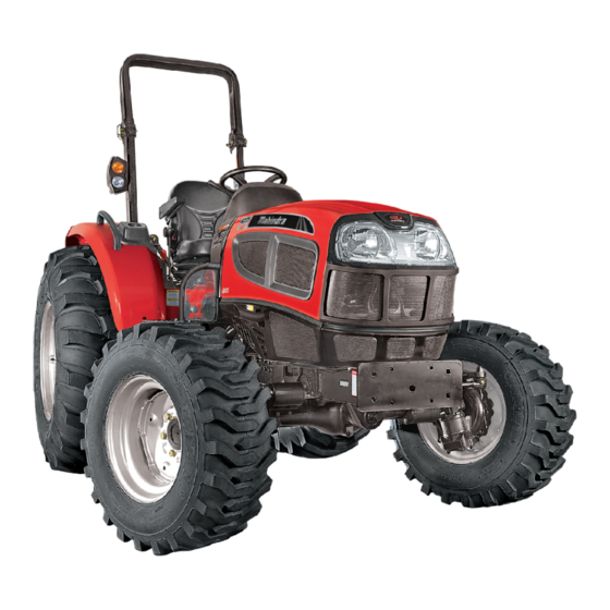
- Page 1 OPERATOR’S MANUAL '35' Series 4WD 3535 / 4035 / 4535 / 5035...
- Page 2 The engine exhaust from this product contains chemicals known to the State of California to cause cancer, birth defects or other reproductive harm. The state of California requires the above two warnings. 35 Series-HST, Model - 3535, 4035, 4535 & 5035...
-
Page 3: Table Of Contents
PTO Auto / Manual / Off Switch Toplink Power Take Off Draft Sensing Bracket Controls Telescopic Lower Links Operator Seat Adjustable Lift Rod RH Adjusting Seat Position Lateral Stabilizers Weight Adjustment Lift Rod LH 35 Series-HST, Model - 3535, 4035, 4535 & 5035... - Page 4 Hydraulic & Transmission Suction Oil Filter 75 Water Pump Hydraulic & Transmission Strainer Hose Connections Transmission Oil Drain Fan & Fan Belts Hydrostatic Transmission (HST) Oil Filter Draining the System Transmission Oil Cooler 35 Series-HST, Model - 3535, 4035, 4535 & 5035...
- Page 5 Brakes Transmission Rear Wheels Electricals Power Steering Tractor History Card Service Record Part Replacement Record Daily Operating Log Tractor Storage Precautions Lubrication & Greasing Chart Routine Service Schedule Electrical Circuit Layout 35 Series-HST, Model - 3535, 4035, 4535 & 5035...
-
Page 6: Emission Control Warranty For California
(the emission control system parts) your owner’s manual. Mahindra & Mahindra Limited to the extent these parts were present on the engine recommends that you retain all receipts covering purchased. 35 Series-HST, Model - 3535, 4035, 4535 & 5035... - Page 7 Add-on or modified parts may not be used. Such b) Any warranted part which is scheduled only for use shall be grounds for disallowing a warranty regular inspection shall be warranted for the 35 Series-HST, Model - 3535, 4035, 4535 & 5035...
- Page 8 Mahindra & Mahindra Limited Emission Control System Warranty. c) Transportation to and from the Mahindra & Mahindra Limited Commercial and Consumer Equipment Retailer, or service calls made by the Retailer. 35 Series-HST, Model - 3535, 4035, 4535 & 5035...
- Page 9 35 Series-HST, Model - 3535, 4035, 4535 & 5035...
-
Page 10: Emission Control Warranty For Federal
& Mahindra Limited recommends that you retain all • Turbocharger system receipts covering maintenance on your non-road diesel equipment engine, but Mahindra & Mahindra • Charge Air Cooling Systems Limited cannot deny warranty solely for lack of 35 Series-HST, Model - 3535, 4035, 4535 & 5035... - Page 11 Transportation to and from the Mahindra & remainder of the period prior to the first Mahindra Limited Commercial and Consumer scheduled replacement point for that part. Equipment Retailer, or service calls made by the Retailer. 35 Series-HST, Model - 3535, 4035, 4535 & 5035...
- Page 12 PURPOSE, EXPRESSLY LIMITED EMISSION CONTROL SYSTEM WARRANTY TERMS SET FORTH IN THIS DOCUMENT. c) No dealer is authorized to modify this Federal and Mahindra & Mahindra Limited Emission Control System Warranty. 35 Series-HST, Model - 3535, 4035, 4535 & 5035...
- Page 13 35 Series-HST, Model - 3535, 4035, 4535 & 5035...
-
Page 14: About This Manual
All data given in this book is subject to production variations. Dimensions & weight are approximate only and the illustrations do not necessarily show tractors in standard condition. For exact information about any particular tractor, please consult your Mahindra dealer. 35 Series-HST, Model - 3535, 4035, 4535 & 5035... -
Page 15: Introduction
Power Take Off or PTO shaft. In this book the operation and maintenance instructions for 35 Series HST models of Mahindra diesel tractors have been compiled. This material has been prepared in detail to help you in better understanding of maintenance and efficient operation of the machine. - Page 16 When spare parts are required, always specify the tractor model and tractor serial number. This will facilitate faster delivery and help ensure that the correct part for your particular tractor is received. 35 Series-HST, Model - 3535, 4035, 4535 & 5035...
-
Page 17: General Description
The rear wheels are bolted to the outer flange of the rear axle. The rear track adjustment is provided on the rear wheel rim. 35 Series-HST, Model - 3535, 4035, 4535 & 5035... -
Page 18: Owner Assistance
Owner Assistance We at Mahindra USA Inc. and your Mahindra Dealer want you to be completely satisfied with your investment. Normally any problems with your equipment will be handled by your Dealer’s service department. Sometimes, however, misunderstanding can occur. If you feel that your... -
Page 19: Owner's Personal Data
Nearest authorised Dealer Name Address Telephone No. : Fax No. Keep this operators manual safely for regular reference. Ensure that all operators have access to it and that they understand its contents. 35 Series-HST, Model - 3535, 4035, 4535 & 5035... -
Page 20: Rops
R O P S Roll Over Protective Structure (ROPS) Mahindra USA Inc. tractors are fitted with a frame for the protection of tractor operator to minimize serious operator injury resulting from accidental roll over. These frames, When improperly operated, a tractor can roll known as ROPS, form a safety zone within which the over. -
Page 21: Safety Instructions
Slow down before you make a sharp turn. Driving forward out of a ditch or mired condition could cause tractor to tip over backward. Back out of these situations if possible. 35 Series-HST, Model - 3535, 4035, 4535 & 5035... - Page 22 Keep PTO shields in place at all times. Wear close fitting clothing. Stop the engine and be sure drive stopped before making adjustments, connections, or cleaning out PTO driven equipment. 35 Series-HST, Model - 3535, 4035, 4535 & 5035...
- Page 23 4. Do not add water to electrolyte as it may splash off causing severe burns. If you spill acid on yourself : 1. Flush your skin with water. 2. Flush your eyes with water for 10-15 minutes. Get medical attention immediately. 35 Series-HST, Model - 3535, 4035, 4535 & 5035...
- Page 24 PTO switch is in OFF position. For additional safety, keep the engine starting key in OFF position, transmission in neutral position, hand brake lever engaged, PTO switch in OFF position while servicing the tractor. 35 Series-HST, Model - 3535, 4035, 4535 & 5035...
-
Page 25: Safety Signs
Safety Signs 35 Series-HST, Model - 3535, 4035, 4535 & 5035... - Page 26 Safety Signs 35 Series-HST, Model - 3535, 4035, 4535 & 5035...
- Page 27 Safety Signs 35 Series-HST, Model - 3535, 4035, 4535 & 5035...
- Page 28 Safety Signs 35 Series-HST, Model - 3535, 4035, 4535 & 5035...
-
Page 29: Universal Symbols
Transmission oil temperature Horn Power take off Parking brake engaged Engine oil Power take off Work lamps pressure disengaged Air filter Lift arm/raise Differential lock Battery charge Lift arm/lower See operator's manual 35 Series-HST, Model - 3535, 4035, 4535 & 5035... -
Page 30: Lh & Rh View Of Engine
3. Oil Filling Port 4. Rotary Fuel Injection Pump 5. Starter Motor 6. Fuel Filter RH View : 1. Exhaust Muffler 2. Alternator 3. Steering Pump 4. Hitch Pump 5. Oil Filter Engine 35 Series-HST, Model - 3535, 4035, 4535 & 5035... -
Page 31: Lamps
3. Reflector & Rear Position Lamp LH 4. Rear Brake Lamp LH 5. Turn Signal Lamp RH 6. Reflector & Rear Position Lamp RH 7. Rear Brake Lamp RH 8. Seven Pole Socket 35 Series-HST, Model - 3535, 4035, 4535 & 5035... -
Page 32: Controls, Instruments & Operations
Switches The operator must be thoroughly acquainted with the location and use of all instruments and controls regardless of experience, must read this section carefully before attempting to operate the tractor. 35 Series-HST, Model - 3535, 4035, 4535 & 5035... -
Page 33: Instrument Cluster
LH / RH Turn Signal Indicator Coolant Temperature Gauge Fuel Level Gauge Engine RPM Meter Hour Counter Engine Low Oil Pressure Gauge Voltmeter Battery Charge Indicator 10. 4WD Indicator 11. Parking Brake Indicator 12. Heater Indicator 35 Series-HST, Model - 3535, 4035, 4535 & 5035... -
Page 34: Rpm Meter
When the pointer lies in RED band : 1. Indicates excessive engine coolant temperature. 2. Get the cause identified. 3. Further engine operation should be done only after elimination of the problem. 35 Series-HST, Model - 3535, 4035, 4535 & 5035... -
Page 35: Turn Indicators
RED Zone. When the Engine is running and healthy it should be in GREEN Zone. If the pointer is in RED Zone, the problem should be eliminated before starting the engine. 35 Series-HST, Model - 3535, 4035, 4535 & 5035... -
Page 36: Switches
The piano type switch is located below the starter key switch on RH side of steering column on dashboard. position operates turn signal lamps simultaneously. This operation can be performed even if the key switch is in OFF position. 35 Series-HST, Model - 3535, 4035, 4535 & 5035... -
Page 37: Combination Switch
It is a 2 positions rotary switch located in LH side of steering column on dashboard. It operates in clockwise direction and positions are as follows: 1. Off 2. Illuminates the plow lamp 35 Series-HST, Model - 3535, 4035, 4535 & 5035... -
Page 38: Pto On/Off Switch
PTO shaft will become operative and will be some Inadvertent movement of personnel near indicated by a CONTINUOUSLY-GLOWING "PTO Engage - the PTO shaft can prove fatal. Disengage Switch". 35 Series-HST, Model - 3535, 4035, 4535 & 5035... -
Page 39: Power Take Off
Refer table shown for combinations of PTO Operations. PC Lever PTO Switch PTO Shaft ON / OFF Switch Control Switch Manual Mode Either raised or lowered Glows Rotates Auto Mode Raised Blinks Stationary Auto Mode Lowered Glows Rotates 35 Series-HST, Model - 3535, 4035, 4535 & 5035... -
Page 40: Controls
12. Slow Fast Valve Control Knob Brake Pedal LH Forward Pedal 13. 4WD Engagement Lever Hand Throttle Position Control Lever 14. Range Shift Lever Parking Brake Lever 10. Draft Control Lever 15. Differential Lock Pedal 35 Series-HST, Model - 3535, 4035, 4535 & 5035... -
Page 41: Operator Seat
This knob is also called implement lock. When the knob is fully tightened in, implement will not lower down even if position control lever is fully down. Use implement lock while transporting implement. 35 Series-HST, Model - 3535, 4035, 4535 & 5035... -
Page 42: Hand Throttle Operation
Forward Reverse Can Holder A Can holder is located on RH side of fender. Glove Box A small utility box is located on LH side of fender. 35 Series-HST, Model - 3535, 4035, 4535 & 5035... -
Page 43: Tilt Steering
1. Stop the tractor motion completely. 2. Lift the lever upwards to engage the drive. 3. Push the lever down to disengage the drive. Disengaged Position engage disengage Engagement lever while the tractor is in motion. 35 Series-HST, Model - 3535, 4035, 4535 & 5035... -
Page 44: Brake
Check for indicator lamp on the instrument cluster implements ground. Leaving when the parking brake is released. The indicator light transmission in gear with engine stopped will not prevent the tractor from rolling. should be 'OFF'. 35 Series-HST, Model - 3535, 4035, 4535 & 5035... -
Page 45: Differential Lock Pedal
1. Choose High / Medium / Low range to match work application. Refer Specification for road speed of tractor in different ranges. Never shift Range shift lever while the tractor is in motion. 35 Series-HST, Model - 3535, 4035, 4535 & 5035... -
Page 46: Cruise Control Lever
2. To direct the hydraulic oil flow to ‘B’ Port, move the lever in the backward direction (B). Aux Valve Lever Positions 3. The lever will return to neutral position (N) when it is released at forward or backward position. 35 Series-HST, Model - 3535, 4035, 4535 & 5035... -
Page 47: Loader
2. Lift the hood upwards by hand. A gas spring provided inside will assist in minimising the effort for lifting. Closing the Hood 1. Ensure that side panels are properly locked. 2. Press the hood downwards till it gets locked. 35 Series-HST, Model - 3535, 4035, 4535 & 5035... -
Page 48: Removing Side Panels
At this stage air cleaner has to be cleaned / Serviced. After servicing, reset the clog indicator by pressing rubber cap. (As marked in the figure). Ensure red band will move to the original position after resetting. 35 Series-HST, Model - 3535, 4035, 4535 & 5035... -
Page 49: Hydraulic System & Operation
5. Lateral Stabiliser LH 6. Lift Arm RH 7. Draft Sensing Bracket 8. Adjustable Lift Rod RH 9. Lower Link RH 10. Lateral Stabiliser RH 11. Drawbar 12. Towing Pin Tractor Front 35 Series-HST, Model - 3535, 4035, 4535 & 5035... -
Page 50: Position Control-Operation
4. Set the position control stop screw (C) against the PC lever and tighten the knob. Whenever the PC lever is returned to the front position till the stopper, the implement will return to the same preset height. Tractor Front 35 Series-HST, Model - 3535, 4035, 4535 & 5035... -
Page 51: Draft Control - Operation
If the rear wheel drops into a furrow, the reverse will occur. Thus under all operating conditions, the “Vary-Touch” system provides maximum traction and constant implement depth. 35 Series-HST, Model - 3535, 4035, 4535 & 5035... -
Page 52: Three Point Linkage
4. Connect lower links to the implement. Sit on operator’s seat and start engine. 5. Back tractor until each lock lever snaps and secures each lower link in the lock position. 35 Series-HST, Model - 3535, 4035, 4535 & 5035... -
Page 53: Adjustable Lift Rod Rh
To adjust the height of the lower link, remove locking pin out of the lift rod-Lower link and adjust the height by putting the locking pin in the required hole as needed. 35 Series-HST, Model - 3535, 4035, 4535 & 5035... -
Page 54: Attachments
Avoid overloading PTO shaft. drawbar. Ballast the tractor for improved 7. Reassemble the PTO shield. stability. Engage the clutch smoothly, avoid jerking and use brakes cautiously to avoid jack- knifing. 35 Series-HST, Model - 3535, 4035, 4535 & 5035... -
Page 55: Drawbar
4035 4535 5035 Drawbar Hole Positions Dist. of Implement Pin Hole from PTO shaft end inch 19.69 13.78 19.69 13.78 19.69 13.78 19.69 13.78 Max. Vertical Load On Drawbar 1036 1143 35 Series-HST, Model - 3535, 4035, 4535 & 5035... -
Page 56: Wheel Tread Adjustment
56.25 (F) 59.84 (J) 56.25 (F) * Standard Track Settings An arrow is marked on the sidewall of the tire, which must always point in the direction of forward rotation to obtain maximum traction. 35 Series-HST, Model - 3535, 4035, 4535 & 5035... -
Page 57: Pneumatic Tires
19.5 x 24, 8PR, R4, TIT Industrial 3000 @ 1.10 3912 5035 Front 9.5 x 20, 6PR, R1 HTL 750 @ 2.11 2870.20 Rear 16.9 x 24, 6PR, R1 HTL 1855 @ 0.94 3987.8 35 Series-HST, Model - 3535, 4035, 4535 & 5035... -
Page 58: Care Of Tires
Use a safety cage, lead to early tire failure. if available. Inflation pressure affects the amount of weight that a tire may carry. Do not over or under inflate the tires. 35 Series-HST, Model - 3535, 4035, 4535 & 5035... -
Page 59: Operating Instructions
In cold weather, idle the engine and warm-up for 5 minutes range which allows the HST to maintain lower at approx. 2000 rpm before loading. pressures and work more efficiently. 35 Series-HST, Model - 3535, 4035, 4535 & 5035... -
Page 60: Driving The Tractor
1 min. and shut drain into a container. Fill the system with off the engine. Remove the key and apply the calibrating oil (if available) of 4 US gallon (15 lit.) parking brake. quantity. 35 Series-HST, Model - 3535, 4035, 4535 & 5035... -
Page 61: Precautions
15. Dim tractor Head lamps when meeting a vehicle at night. Be sure the Head lamps are adjusted to prevent blinding on the eyes of oncoming vehicle operator. 35 Series-HST, Model - 3535, 4035, 4535 & 5035... -
Page 62: The Tractor
7. Always check overhead clearance, especially when 10. Do not short the Alternator output leads to check transporting the tractor. its working. 35 Series-HST, Model - 3535, 4035, 4535 & 5035... -
Page 63: Operating The Pto (Power Take Off)
2. Before descending a hill, shift to a gear low enough to control tractor travel speed without having to use the brake pedals to brake the tractor and installed attachments. 35 Series-HST, Model - 3535, 4035, 4535 & 5035... -
Page 64: Do's & Dont's
DO - Refer loader operator's manual for safe operation and trouble free performance. 35 Series-HST, Model - 3535, 4035, 4535 & 5035... -
Page 65: Maintenance
When installing a Do not run the Engine without Thermostat new thermostat, ensure the valve is facing upward. The Valve. thermostat operating temperature is 180 35 Series-HST, Model - 3535, 4035, 4535 & 5035... -
Page 66: Water Pump
7.0 litres (1.84 US Gallons) of water. Do not replace the radiator cap. Operate the engine until the coolant is hot. Drain, flush with clean water and refill with a rust inhibitor or anti-freeze solution. 35 Series-HST, Model - 3535, 4035, 4535 & 5035... -
Page 67: Adding Coolant To The System
Full Force Conoco Fleet Antifreeze (with 13 psi (0.91kg/cm ) radiator cap) Northern Petrochemical All Weather Recommended change period : 1 year or (NPC 220) when ever the radiator water is drained. 35 Series-HST, Model - 3535, 4035, 4535 & 5035... -
Page 68: Trashguard
Reassemble the valve housing and ensure that the valve Clearance 0.25 housing gasket makes an oil tight seal with the cylinder (Cold Values) Inch 0.01 0.012 head. Use a new gasket, if necessary. 35 Series-HST, Model - 3535, 4035, 4535 & 5035... -
Page 69: Air Intake System
Do not use dirty or damaged paper element as the impure air may severely reduce the engine performance/ life. Hose and Clamps Check Hose clamps for proper tightness. Safety Cartridge 35 Series-HST, Model - 3535, 4035, 4535 & 5035... -
Page 70: Fuel System
In order to prevent tampering, a tamper-proof arrangement is provided on Fuel Injection Pump consisting of SPECIAL SEALS (C). Any FIP related work should be carried at Mahindra / BOSCH authorised dealership. 35 Series-HST, Model - 3535, 4035, 4535 & 5035... -
Page 71: Fuel Filter
5. Assemble the new filter. Do not over tighten. Always fit the spin-on filter dry. 6. Prime the system and bleed the filter. Tighten the bleeding screw. 35 Series-HST, Model - 3535, 4035, 4535 & 5035... -
Page 72: Lubrication System
Note : Stop the engine immediately if Oil pressure is not recorded within 10 seconds of engine starting or Leakage is observed. Get the cause identified and rectified before proceeding further. 35 Series-HST, Model - 3535, 4035, 4535 & 5035... -
Page 73: Electrical System
Maintaining the electrical system in good working order will enable the alternator to provide the current needed necessary to keep battery fully charged thus ensuring maximum efficiency of the electrical devices. 35 Series-HST, Model - 3535, 4035, 4535 & 5035... -
Page 74: Alternator
The dimension between the leading edge of the pinion and the engine flywheel should be no less than 0.32 cms. 35 Series-HST, Model - 3535, 4035, 4535 & 5035... -
Page 75: Hydraulics & Transmission
To top-up oil in the front axle, open the dipstick (B) on both sides of swivel housing and refill oil via filling port (E) upto the required level and refit the dipstick. Ensure tightening the dipstick properly. Oil Filling Location 35 Series-HST, Model - 3535, 4035, 4535 & 5035... -
Page 76: Hydraulic & Transmission Suction Oil Filter
For Service / Replacement of strainer contact your Mahindra Dealer. Transmission Oil Drain Drain plug (C) is provided on the transmission for draining transmission oil. The drain plug located at the bottom of the transmission case. 35 Series-HST, Model - 3535, 4035, 4535 & 5035... -
Page 77: Hydrostatic Transmission (Hst) Oil Filter
6. Do not repair the cooler if it is leaking. Incase of leakage, replace with new unit. 7. Do not try to tilt elbow / toil ports as these are brazed to avoid physical damage. 8. Do not use damaged oil cooler. 35 Series-HST, Model - 3535, 4035, 4535 & 5035... -
Page 78: Toe-In Setting
Measure again the distance between these two points and this distance must be the same as measured before without variance. To adjust the TOE-IN shorten or extend the tie rod clockwise or anti-clockwise. 35 Series-HST, Model - 3535, 4035, 4535 & 5035... -
Page 79: Brake Pedal Free Play
Free Play - Distance 1.57 to 1.77 inch (40 to 45 mm) 1. Loosen jam nut (B). 2. Turn the Turn Buckle (C) anti-clockwise to increase play and clockwise to decrease play. Brake Setting from RH Side Brake Setting from LH Side 35 Series-HST, Model - 3535, 4035, 4535 & 5035... -
Page 80: Head Lamp Adjustment
6. Turn light switch to dim position. 7. Locate point (E) of bright light projected by each lamp by adjusting screws (W), (X), (Y) and (Z) as required. Cover other lamps, if necessary. Bright Light Area 35 Series-HST, Model - 3535, 4035, 4535 & 5035... -
Page 81: Lubricants
Please note that engine breathes even while it is not running and once condensation take place rapid deterioration of oil may happen. 35 Series-HST, Model - 3535, 4035, 4535 & 5035... -
Page 82: Engine Oil
This will allow the oil to work into the bearings and onto the cylinder walls. * Factory filled oil is 15W40 and may change in future. * Factory filled oil is Enclo 46 and may change in future. 35 Series-HST, Model - 3535, 4035, 4535 & 5035... -
Page 83: Transmission, Hydraulics
NLGI No. as recommended Front Axle - 3535 1.71 / 6.84 SAE75W90EP SAE80W140EP SAE80W90EP SAE80W140EP 4035, 4535 & 5035 2.24 / 8.96 SAE80W90EP listed above for ambient temperature range - 4 F to 104 35 Series-HST, Model - 3535, 4035, 4535 & 5035... -
Page 84: Special Bolt Torques
Bolt front wheel 85 - 96 115 - 130 Bolt for semi chassis mounting Transmission drain plugs 51 - 57 70 - 77 Axle mounting bolts 221 - 258 300 - 350 35 Series-HST, Model - 3535, 4035, 4535 & 5035... -
Page 85: Specifications
Mechanical Front Wheel Drive (MFWD) with Bevel Gear Front and Rear Position, Final Reduction. Brake Lamp, Plow Lamp. Heater Plug System for : Main Components : Cold Starting 1. Heater Plug 2. Timer Relay 35 Series-HST, Model - 3535, 4035, 4535 & 5035... - Page 86 Note : Roll over protection structure is standard fitment on all tractors. Note : Specifications and design subject to change without notice. * Manufacturer's estimate under standard condition and subject to change without prior notice. 35 Series-HST, Model - 3535, 4035, 4535 & 5035...
- Page 87 Mechanical Front Wheel Drive (MFWD) with Bevel Gear Front and Rear Position, Final Reduction. Brake Lamp, Plow Lamp. Heater Plug System for : Main Components : Cold Starting 1. Heater Plug 2. Timer Relay 35 Series-HST, Model - 3535, 4035, 4535 & 5035...
- Page 88 Note : Roll over protection structure is standard fitment on all tractors. Note : Specifications and design subject to change without notice. * Manufacturer's estimate under standard condition and subject to change without prior notice. 35 Series-HST, Model - 3535, 4035, 4535 & 5035...
- Page 89 Mechanical Front Wheel Drive (MFWD) with Bevel Gear Front and Rear Position, Final Reduction. Brake Lamp, Plow Lamp. Heater Plug System for : Main Components : Cold Starting 1. Heater Plug 2. Timer Relay 35 Series-HST, Model - 3535, 4035, 4535 & 5035...
- Page 90 Note : Roll over protection structure is standard fitment on all tractors. Note : Specifications and design subject to change without notice. * Manufacturer's estimate under standard condition and subject to change without prior notice. 35 Series-HST, Model - 3535, 4035, 4535 & 5035...
- Page 91 Mechanical Front Wheel Drive (MFWD) with Bevel Gear Front and Rear Position, Final Reduction. Brake Lamp, Plow Lamp. Heater Plug System for : Main Components : Cold Starting 1. Heater Plug 2. Timer Relay 35 Series-HST, Model - 3535, 4035, 4535 & 5035...
- Page 92 Note : Roll over protection structure is standard fitment on all tractors. Note : Specifications and design subject to change without notice. * Manufacturer's estimate under standard condition and subject to change without prior notice. 35 Series-HST, Model - 3535, 4035, 4535 & 5035...
-
Page 93: Trouble Shooting
Check air cleaning system. Restriction in exhaust ............. Clean exhaust system. Restriction in fuel supply ..........Clean fuel system. Water in the fuel ............Drain and clean fuel system. 35 Series-HST, Model - 3535, 4035, 4535 & 5035 * See Mahindra Tractor Dealer... - Page 94 Inspect fuel system. Clean out fuel lines. Injection nozzles defective ..........Injection timing incorrect ..........Excessive wear on throttle shaft ........Poor compression ............Sticking valves ..............Governor inoperative ............35 Series-HST, Model - 3535, 4035, 4535 & 5035 * See Mahindra Tractor Dealer...
- Page 95 Faulty radiator cap ............Have service person check. Dirty radiator core or grille screens ....... Remove all trash. Defective thermostat ............Remove and check thermostat 35 Series-HST, Model - 3535, 4035, 4535 & 5035 * See Mahindra Tractor Dealer...
- Page 96 Check and rectify Air leak between intake manifold and engine ....Check and rectify Foreign object in exhaust manifold (from engine) ..Restricted exhaust system ..........35 Series-HST, Model - 3535, 4035, 4535 & 5035 * See Mahindra Tractor Dealer...
-
Page 97: Hydraulics
Control valve/linkage defects .......... System Overheating Air in the system ............Locate the source of air entry and seal it. Water in the system ............Drain oil & refill. 35 Series-HST, Model - 3535, 4035, 4535 & 5035 * See Mahindra Tractor Dealer... -
Page 98: Brakes
PTO engaged ..............Disengage PTO. Starter Cranks Slowly Low battery output ............Check electrolyte level and specific gravity. Crankcase oil too heavy ..........Use proper viscosity oil. 35 Series-HST, Model - 3535, 4035, 4535 & 5035 * See Mahindra Tractor Dealer... -
Page 99: Power Steering
Check for air in the hydraulic system & bleed it. Excessive heat (200ºF Maximum) ........Check for correct size of hose. Check for the centering of control unit. Check for excessive fluid flow. 35 Series-HST, Model - 3535, 4035, 4535 & 5035... -
Page 100: Tractor History Card
Tractor History Card Nature of W/Claim No. Date Card No. Parts Replaced Remarks Defect and Date 35 Series-HST, Model - 3535, 4035, 4535 & 5035... -
Page 101: Service Record
Service Record Date Tractor Hours Nature / Type of Repair / Service Carried Out 35 Series-HST, Model - 3535, 4035, 4535 & 5035... -
Page 102: Part Replacement Record
Part Replacement Record Date Part Description Cost Date Part Description Qty. Cost 35 Series-HST, Model - 3535, 4035, 4535 & 5035... -
Page 103: Daily Operating Log
Daily Operating Log Machine Hours Fuel Engine Oil Date Job Done Remarks Consumed Topped Up Start 35 Series-HST, Model - 3535, 4035, 4535 & 5035... - Page 104 Daily Operating Log Machine Hours Fuel Engine Oil Date Job Done Remarks Consumed Topped Up Start 35 Series-HST, Model - 3535, 4035, 4535 & 5035...
-
Page 105: Tractor Storage Precautions
& contamination. b) If the tractor is standstill ( not run ) for more than 3 months then It is recommended to replace the Diesel to avoid detoriation in the performance. 35 Series-HST, Model - 3535, 4035, 4535 & 5035... -
Page 106: Lubrication & Greasing Chart
Engine Oil Filling Port Trans/Hydraulic Oil Level Check Trans/Hydraulic Oil Drain Plug 10/12 Trans/Hydraulic Oil Filling Port Front Axle Oil Level Check Front Axle Oil Drain Plug Front Axle Oil Filling Port 35 Series 4WD-HST, Model - 3535, 4035, 4535 & 5035... -
Page 107: Routine Service Schedule
Every 50 Hrs. * Depends upon the conditions in which the tractor is being operated. Activity due. 35 Series 4WD-HST, Model - 3535, 4035, 4535 & 5035 # Indicates that this must be done initially at specified hrs. Repeat the activity. -
Page 108: Electrical Circuit Layout
Wiring Diagram - 35 Series HST 35 Series 4WD-HST, Model - 3535, 4035, 4535 & 5035...
Need help?
Do you have a question about the 3535 and is the answer not in the manual?
Questions and answers