Table of Contents
Advertisement
Quick Links
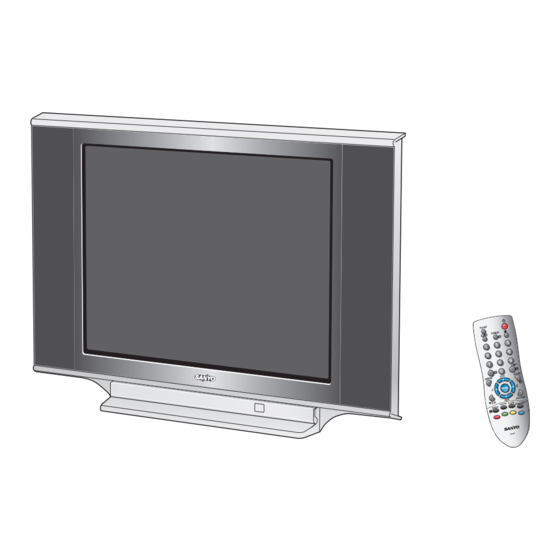
SERVICE MANUAL Colour Television
Specifications
Power Source
. . . . . . . .AC110-240V, 50/60Hz.
Colour System . . . . . . . .PAL, SECAM, NTSC4.43, NTSC, PAL 60Hz
Television System . . . . .B/G, D/KK', I, M/M
Channel Coverage . . . . .VHF: E2-E12, R1-R12, K1-K9, J1-J12, A2-A13
UHF: 21-69, A14-A69, J13-J62
CATV: S1-S41, X, Y, Z, Z+1, Z+2
Video IF . . . . . . . . . . . . . .38.0 MHz
Aerial Input Impedance . 75Ω
Ext. Terminals
Video inputs: Phono jack 2 (1.0Vp-p, impedance 75Ω)
S-Video Input 1 (Din 4 pin, Separate Y/C Signals Input)
DVD Input: Component Video Jack-Y 1 (1.0Vp-p, impedance 75Ω)
Component Video Jack CB/CR 1 (0.7Vp-p, impedance 75Ω)
Audio inputs: Phono jack (R/L) 3 (436mVrms, impedance more than 40KΩ)
Video monitor output: Phono jack 1 (1.0Vp-p, 75Ω)
Audio monitor outputs: Phono jack(R/L) 1(436mVrms, Impedance less than
600Ω)
Headphone jack: Mini Stereo jack 1
Speaker
Main speaker . . . . . . . 6cm 12cm 2 pcs.
Tweeter . . . . . . . . . . . . ∅ 5cm 2 pcs.
Sound Output (RMS) . . . 7.5W + 7.5W
Dimensions . . . . . . . . . . . 803 (W) 578 (H) 418 (D)mm
Weight . . . . . . . . . . . . . . . approx. 41.5 Kg
Specifications subject to change without notice
C8ZH
FILE NO.
Model No. CE29FS2
Service Ref. No. CE29FS2-00
Product Code: 111379407
Original Version
Chassis Series: FB1-B
Give complete "SERVICE REF. NO." for parts
order or servicing. It is shown on the rating plate
at the cabinet back of the unit.
This T.V. receiver will not work properly in
foreign countries where the television
transmission system and power source dif-
fer from the design specifications. Refer to
the specification table.
REFERENCE NO.
(RUSSIA)
SM
3010185
Advertisement
Table of Contents

Related Manuals for Sanyo CE29FS2


Summary of Contents for Sanyo CE29FS2
- Page 1 FILE NO. SERVICE MANUAL Colour Television Model No. CE29FS2 (RUSSIA) Service Ref. No. CE29FS2-00 Product Code: 111379407 Specifications Power Source ..AC110-240V, 50/60Hz. Colour System ..PAL, SECAM, NTSC4.43, NTSC, PAL 60Hz Television System .
-
Page 2: Table Of Contents
Contents Safety Notice ..........2 Chassis Block Diagram . - Page 3 IC802 EEPROM TUNER IC701 VIDEO Q901 TRIPLE VIDEO OUTPUT VIDEO IC201 PROCESSOR IC501 VERTICAL T431 H-DRIVE TRANS Y-IN Q431 Q432 Cb-IN H-DRIVE H-OUT Cr-IN T471 CIRCUIT VIDEO IC1401 WOOFER AMP. IC001 AUDIO AMP. KEY SW RECEIVER WOOFER H-PHONE SPEAKER...
- Page 4 IC001 SOUND MUTE AUDIO AMP. COLOUR SYSTEM OPTION INPUT RESET INPUT (RESET=LOW) KEY SWITCH IN IC201 SWITCH IC3701 QXXAVC534C7JAS QXXAVC534M AUDIO CONTROL/ IC1201 VIDEO SELECTOR SURROUND (LOW=AV1, H=AV2) VIDEO SELECTOR 13 14 SECAM KILLER INPUT (HIGH=SECAM) A101 F/S TUNER BILINGUAL OUTPUT (LOW=S-1, HIGH=S-2) POWER ON/OFF (ON=HIGH, OFF=LOW) PHOTO COUPLE...
- Page 5 QSSO/AMOUT SSIF SCART/CINCH IN/OUT LS-OUT HP-OUT REFO AUDIO CONTROL SWITCH A/D CONVERTER SOUND PLL QSS SOUND IF VOLUME AUDIO SELECT ALL-STANDARD SIFIN/DVBIN TREBBLE/BASS STEREO ADC/DAC DEEMPHASIS QSS MIXER FEATURES AM DEMODULATOR DECODER DVBO/IFVO/ FMRO DVBO/FMRO AGCOUT VISION IF/AGC/AFC µ-PROCESSOR AND TELETEXT DECODER PLL DEMOD.
-
Page 6: Ic Block Diagrams
IC Block Diagrams IC001 < Audio AMP.> TDA8947J/N3 VCC1 VCC2 OUT1+ IN1+ 60 kΩ IN2+ OUT2- 60 kΩ IN3+ OUT3- 60 kΩ IN4+ OUT4+ 60 kΩ SHORT CIRCUIT TEMPERATURE PROTECTION 0.5Vcc Vref SGND STANDBY ALL MODE1 MUTE ALL TDA8947J ON 1+2 MUTE 3+4 MODE2 ON 3+4... -
Page 7: Cpu Port Functions
CPU Port Functions Pin No. Function Name Function Pin No. Function Name Function VSSP2 Ground DVBO/IFVO/FMRO Digital Video Broadcast output / IF VSSC4 Ground video output / FM radio output VDDC4 Digital supply to SDACs (1.8V) DVBO/FMRO Digital Video Broadcast output / FM radio output VDDA3(3.3V) Supply (3.3V) -
Page 8: Cpu Port Functions
CPU Port Functions Pin No. Function Name Function Pin No. Function Name Function 3 rd G input / Y input P3.3/ADC3 Port 3.3 or ADC3 input G/YIN3 3 rd B input / P VSSC/P Digital ground for µ-Controller core input and periphery GND3 Ground 3 for TV-processor... -
Page 9: Option Setting
Option Setting After replacing the Memory IC (IC802) The memory IC (IC802), stores the option data of TV set and service adjustments data for each circuit, therefore, when the memory IC is replaced, it should be programmed to the following settings and “ SERVICE ADJUSTMENT” on pages 15 to 16. -
Page 10: Service Adjustments With Replacing Memory Ic(Ic802)
Service Adjustments with Replacing Memory IC(IC802) Note: The CPU (IC201) and memory IC (IC802) store the service adjustments data and controls data for each circuit.When the Memory IC(IC802) is replaced, some of the service adjustments should be readjusted to obtain the best performance. The necessary service adjustments are carried out by using the RC handset. Please set up the TV set with following steps [1] to [2]. - Page 11 Service Adjustments with Replacing Memory IC(IC802) 1) To enter to the Service Mode 1. Press and hold the Volume + button on the front of TV set and press the Menu button on the Remote Control. Display for Software Version Information TV/AV MENU SERVICE 001 FB1B...
- Page 12 Service Adjustments with Replacing Memory IC(IC802) Following table shows the initial values which have been stored in the CPU ROM, and items for the service adjustments. Service mode adjustments table in CPU ROM DATA INITIAL DATA INITIAL ITEM RANGE SETUP DESCRIPTION ITEM RANGE SETUP...
- Page 13 Service Adjustments with Replacing Memory IC(IC802) Following table shows the initial values which have been stored in the CPU ROM, and items for the service adjustments. Service mode adjustments table in CPU ROM DATA INITIAL DATA INITIAL ITEM RANGE SETUP DESCRIPTION ITEM RANGE SETUP...
- Page 14 Service Adjustments with Replacing Memory IC(IC802) Following table shows the initial values which have been stored in the CPU ROM, and items for the service adjustments. Service mode adjustments table in CPU ROM DATA INITIAL DATA INITIAL ITEM RANGE SETUP DESCRIPTION ITEM RANGE SETUP...
-
Page 15: Service Adjustments With Replacing Memory Ic (Ic802)
Service Adjustments with Replacing Memory IC(IC802) Following table shows the initial values which have been stored in the CPU ROM, and items for the service adjustments. Service mode adjustments table in CPU ROM DATA INITIAL DATA INITIAL ITEM RANGE SETUP DESCRIPTION ITEM RANGE SETUP... -
Page 16: Dealer Mode
Dealer Mode Cautions to the dealer!! When the TV will distributed to the market, it should be reset all received channel by following these procedure. 1. Press the TV/AV button on the TV set for a about 2 seconds until “MEMORY CLEAR” is displayed. (displayed in yellow colour) TV/AV MENU MEMORY CLEAR... -
Page 17: Adjustment
Adjustments IMPORTANT NOTICE Do not attempt to adjust the following service adjustments except when adjustments are required in servicing other- wise it may cause loss of performance and product safety. +B VOLTAGE ADJUSTMENT PCC ADJUSTMENT (1) Connect a DC voltmetre to TP-B and the ground. PCC ADJUSTMENT (2) Tune the receiver to an active channel and synchronized pic- (1) Receive cross hatch pattern, set the picture mode to Natural. - Page 18 Adjustments OSD POSITIONING ADJUSTMENT HORIZONTAL ADJUSTMENT HORIZONTAL CENTRING ADJUSTMENT (1) Receive circular pattern and set bright and Contrast to (1) Receive circular pattern and set picture mode to “Dynamic”. Dynamic. (2) Enter to the service mode item No. 22 “HOR.SHIFT”. (2) Enter to the service mode and select item No.
-
Page 19: Purity And Convergence Adjustment
Purity and Convergence Adjustment CAUTION: The Convergence and Purity adjustments have been made at the factory. Readjustment should be made only after picture tube or deflection yoke replacement, following the steps below: Signals: Use a pattern generator which can output red, Rubber wedge Figure 1 green, blue and white raster and crosshatch... -
Page 20: Convergence Adjustment
Purity and Convergence Adjustment CONVERGENCE ADJUSTMENT Figure 5 FOUR-POLE MAGNET TABS Preparation: After carrying out purity adjustment and SIX-POLE MAGNET TABS before proceeding to convergence adjustment, provisionally insert the rubber wedge so that there is no vertical or ANGLE sideways play in the deflection yoke. OF TABS Signals: Display a crosshatch pattern. -
Page 21: Mechanical Disassembly
Mechanical Disassembly CABINET BACK REMOVAL 1. Refer to Figure 1, remove 13 screws. 2. Pull off cabinet back and remove. Figure 1. Cabinet Back Removal Protection Circuit This TV set has a built-in power supply protection circuit. It is provided to protect the TV set in case of a power supply circuit malfunctions. When something abnormality occurs during TV reception, the TV set goes to the stand-by mode. -
Page 22: Cabinet Parts List
CABINET FRONT-C8ZA 610 323 8616 DOOR-C8ZA 610 324 7922 DOOR COVER SHEET-C8ZA 610 324 7823 DEC SHEET-C8ZA 645 040 4672 BADGE,SANYO*43.5X10L43.5 645 041 7269 BADGE,SANYO*43.5X10L43.5 610 104 2505 LATCH PUSH,7.9X6.9BK 645 019 2449 LATCH PUSH,7.9X6.9BK 610 323 9057 CABINET BACK-C8ZA... -
Page 23: Chassis Electrical Parts List
Chassis Electrical Parts List C8ZH Product safety should be considered when a component replacement is made in any area of a receiver. Components indicated by a mark in this parts list and the circuit diagram show components whose value have special significance to product safety. - Page 24 C8ZH Ref. No. Part No. Description Ref. No. Part No. Description 4051345925 TR 2SA1037AK-T146-R 4050020417 TR 2SA1037K T146 S 4051472215 TR 2SA1037AK-S-T146 4050026726 TR 2SA1179-M6-TB 4050020318 TR 2SA1037K T146 R 4050026924 TR 2SA1179-M7-TB 4050020417 TR 2SA1037K T146 S 4051739615 TR 2SA1235A1E 4050026726 TR 2SA1179-M6-TB 4051739714...
- Page 25 C8ZH Ref. No. Part No. Description Ref. No. Part No. Description 4051631612 TR 2SC2812N-L6-TB0 Q682 4051648412 TR KTC3875S-GR-RTK 4051631711 TR 2SC2812N-L7-TB0 4050144519 TR 2SC2412K T146 R 4051739813 TR 2SC3928A1R 4050144618 TR 2SC2412K T146 S 4051739912 TR 2SC3928A1S 4050158724 TR 2SC2812-L6-TB Q425 4060121408 TR 2SK2010-CTV-YA14...
- Page 26 C8ZH Ref. No. Part No. Description Ref. No. Part No. Description C032 4040848905 ELECT 10U M C232 4031640214 CERAMIC 0.1U Z 4030494224 ELECT 10U M C233 4040849001 ELECT 2.2U M C056 4031576711 CERAMIC 560P K 4030499823 ELECT 2.2U M C1001 4031573611 CERAMIC 100P J...
- Page 27 C8ZH Ref. No. Part No. Description Ref. No. Part No. Description 4033710618 MT-POLYPRO 0.2U J 250V C613 4031792715 POLYESTER 2200P J C427 4033726510 MT-POLYPRO 0.2U J 250V C614 4033486612 POLYPRO 0.02U J 630V C428 4030757121 CERAMIC 1000P K 500V C615 4040876007 ELECT 47U M...
- Page 28 C8ZH Ref. No. Part No. Description Ref. No. Part No. Description C809 4032695916 CERAMIC 0.22U K R128 4011052716 MT-GLAZE 220 JA 1/16W C810 4031552210 CERAMIC 3300P K R129 4011056011 MT-GLAZE 5.6K JA 1/16W C811 4031552319 CERAMIC 4700P K R130 4011050613 MT-GLAZE 10K JA 1/16W C812...
- Page 29 C8ZH Ref. No. Part No. Description Ref. No. Part No. Description R403 4011054314 MT-GLAZE 330K JA 1/16W R603 4011007706 OXIDE-MT 0.22 JA R404 4010247440 CARBON 10K JA 1/6W R604 4012280405 OXIDE-MT 0.27 JA R405 4010272630 CARBON 5.6K JA 1/6W R606 4010632909 OXIDE-MT 68K JA...
- Page 30 C8ZH Ref. No. Part No. Description Ref. No. Part No. Description 4071490817 DIODE 1SS355-TE-17 TRANSFORMER D003 4072128818 DIODE KDS160-RTK T431 6100001077 DRIVE TRANS 4071490817 DIODE 1SS355-TE-17 6102231656 DRIVE TRANS D009 4072128818 DIODE KDS160-RTK 6450473371 TRANS,DRIVE 4071490817 DIODE 1SS355-TE-17 6520000704 TRANS,DRIVE D1001 4070639722 ZENER DIODE MTZJ9.1C...
- Page 31 C8ZH Ref. No. Part No. Description Ref. No. Part No. Description 4070134336 DIODE 1S2076A D802 4070124426 DIODE 1SS133 4070137129 DIODE 1S2473 MISCELLANEOUS D466 4070997822 ZENER DIODE MTZJ20A 4070551717 ZENER DIODE RD20EB1 F601 4230288603 FUSE 250V 4A D467 4080093204 DIODE 1N4148 4230248409 FUSE 250V 4A 4070134336...
- Page 32 C8ZH Ref. No. Part No. Description Ref. No. Part No. Description 4050118619 TR 2SC1740S-S C710 4032819302 ELECT 10U M 250V 4050122012 TR 2SC1815-GR C741 4032636820 CERAMIC 2200P K 4050122111 TR 2SC1815-O 4034140216 CERAMIC 2200P K 4050122319 TR 2SC1815-Y 4050207511 TR 2SC945A-PA RESISTOR 4050207719 TR 2SC945A-QA...
-
Page 33: Component Locations
Component Locations Main Board (Parts Side) IC501A IC501 -33-... -
Page 34: Component Locations
Component Locations CRT Board (Parts Side) K1451 K17J R1466 R1749 C745 IC701-1 C1723 C1719 L1708 R1739 D1455 R1465 R1701 J1707 D1454 D1453 R714 L1707 JW66 D1452 J1455 D712 IC701 R704 C1750 R1735 D702 R724 C1702 C710 C1705 R715 C1748 L721 Q1702 IC1453 C1467... - Page 35 J1020 R1913 D1905 JP1901 R1902 D1906 R1912 J1017 D1903 R887 SW1904 SW1902 SW1901 R1907 A1901 SW1903 D1902 D1901 D850 DESIGN BY MR.SANYO R1011 R1906 D1909 D1003 Q886 JP102 D1001 R1013 D1002 C1001 C1002 J1016 K001 J1015 J1014 L601B-H4 L601B-H3 SW601...
- Page 36 Component Locations CRT Board (Solder Side) K1451 K17J R1466 R1749 C745 IC701-1 C1723 L1708 R1739 D1455 R1465 C1719 R1701 J1707 D1453 D1454 R714 JW66 J1455 D1452 L1707 C1705 D712 R704 IC701 C1750 R1735 D702 R724 C1702 C710 C1748 IC1453 C1751 R715 C1467 L721...
-
Page 37: Voltages And Waveforms Charts
Voltages and Waveforms Charts Note: Voltages and waveforms were measured with colour bar signal and controls adjusted for normal picture. Main Board Q004 Q006 Q007 Q008 Q1005 Q111 Q112 Q113 Q202 Q203 Q204 Q003 E 5.6V E 1.7V E 0.5V 0.4V E 3.3V E 3.3V... -
Page 38: Crt Board
Voltages and Waveforms Charts CRT Board Q1702 Q1706 Q1707 Q1708 Q1712 Q1709 Q1711 3.1V E 0.6V E 10.8V E 10.8V B 141.2V C 19.7V C 19.7V C 10.6V 71.2V C 71.2V B 3.7V B 10.66V E 10.6V B 1.2V E 140.5V 0.8V IC701 (Triple Video Output Amp.) Pin-1 2.2V... - Page 39 8. This circuit diagram covers a basic or representative chassis only. W: Wire wounding Rated wattage (1/2W) POSISTER There SERVICE CE29FS2-00 C: Solid RESISTOR may be some components or partial circuit differences between the REF. NO. 12 X 10 =12K actual chassis and the circuit diagram.
Need help?
Do you have a question about the CE29FS2 and is the answer not in the manual?
Questions and answers