
Related Manuals for KStar KSG-1.5K-SM


Summary of Contents for KStar KSG-1.5K-SM
- Page 1 KSG-1.5K/2K/3K/3.6K-SM KSG-1.5K/2K/3K/3.6K-SM Solar Inverter Solar Inverter User Manual...
-
Page 2: Table Of Contents
Table of Contents 1 User Guide ..................2 2 Safety Instructions ................3 3 Product Warranty ................4 4 Overview ..................5 4.1 Introduction of Grid-connected System ........5 4.2 Brief Introduction of PV Inverter ..........6 4.3 Features Description ..............7 5 Installation ..................8 5.1 Packing ..................8 5.2 Installation of Inverter ..............8 5.3 Installation Location ..............9 5.4 Installation Procedure ..............10... -
Page 3: User Guide
1 User Guide It is appreciating that you purchase KSG single-phase grid-connected inverter produced by KSTAR. The product is non-transforming type inverter, features reliable performance and advanced technology. It converts DC currents from solar arrays into AC currents then fed to municipal Electrical Grid. -
Page 4: Safety Instructions
2 Safety Instructions 1. Electric Shock The product has alternating current (AC) and direct current (DC) connections, in order to avoid any electric shocks during maintenance or before installation, please make sure the disconnection of these AC or DC ports, grounded for solar system and inverter. -
Page 5: Product Warranty
3 Product Warranty The warranty period of these inverters is 2 years. If you would like to extend your warranty period, you can apply for it and keep up warranty card well. The maintenance is free of charge during warranty period. -
Page 6: Overview
4 Overview 4.1 Introduction of Grid-connected System Basically Grid-connected system is comprised of 4 portions: PV array, PV inverter, AC connection unit and Public Grid connection unit. Once PV arrays receive sun shines, they will generate DC current and feed into PV inverter which is confi gured between DC input and municipal AC grid. -
Page 7: Brief Introduction Of Pv Inverter
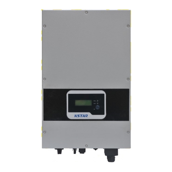
4.2 Brief Introduction of PV Inverter The inverter coverts DC current from solar units into AC current, and feeds to Municipal Electrical Grid. The inverter is designed and produced as per relative requirement of laws and regulations. The shape and functions of relative parts is described as follows: 1. -
Page 8: Features Description
WIFI port.(option) RS232 port: By this interface, user can use computer to communicate with the equipment. There is water proof cover to protect RS232 connectors. DC input ports: Inverters above 3KW have 2 pairs of DC ports, each pair of input ports have positive (+) and negative (-) connector. -
Page 9: Installation
5 Installation 5.1 Packing Please check carefully before opening the package of the equipment. It may cause the inverter damage in case the packing material is found damage, please contact with forwarder for claim. If necessary, Please feel free to contact us. 5.2 Installation of Inverter Please read the following installation instruction before you start your work so as to achieve best effect of the inverter. -
Page 10: Installation Location
5.3 Installation Location The inverter is suitable to be installed on vertical or backwards tilt wall as shown above, the tilt angle should be less 20 ° . Don’t install inverter on forward tilt wall. Don’t install inverter on horizontal wall. Mount the inverter at height same as eyesight for easy operation and data reading. -
Page 11: Installation Procedure
5.4 Installation Procedure Stick the installation formwork from the packing list to the wall. Use ∮ 10 driller kit to drill installation holes with reference of the following photo for the correct position. Clean the dust inside the holes, and insert expansion pipe into the holes. - Page 12 Hang the inverter onto the 4 tapping screws, and check both sides and keep the inverter in right position, then tighten four tapping screws as shown in following pictures.
-
Page 13: Wiring
5.5 Wiring Remove wiring cover in the inverter, you will see below shown connection ports: A,B, Connector for DC input, the polarity sequence is negative, negative, positive, positive (-,-,+,+). Please fi nd label with polarity markers. 1.5K/2K-SM has only one group of positive pole, negative pole and PV terminal in A,D . -
Page 14: Connection Procedure
(4mm ) and the outer diameter of Φ13mm of the photovoltaic cable as the connecting line of the AC output terminal. Cables should avoid high temperature, flame and rain water whenever possible. During connecting the inverter, make sure no connection among AC, DC and any power resources. -
Page 15: Operation Of Grid-Connected Inverter
6 Operation of Grid-connected Inverter... -
Page 16: Trial Operation
6.1 Trial Operation The inverter can be activated only after the following inspections are well executed: Correct connection for AC cables. 2. All solar arrays are connected with the inverter correctly. 3. Tighten all screws. 4. Turn on the breaker between DC and AC. 5. - Page 17 The following example shows the process when PV voltage is increased from 120V: Turn on the inverter, its model and version will be displayed fi rst. 3K-SM The input voltage is less 150V but higher than 120V, the inverter will be in stand- by status.
-
Page 18: Led Display
Fault Status The PV inverter is always under intelligent monitoring condition after it gets started. It will become faulty status when any fault occurs (such as municipal voltage is overload, frequency is over range) or components failure. The faulty information can be displayed by LCD, at that time the red LED is on. -
Page 19: Lcd Display
Error (RED light): it will be on when fault alarm occurs or components failure. If you like to realize more error information, please refer to below chapters. 6.4 LCD Display 1. Button and Back Lighting Operation There are two types of button press,short time press means pressing the button less than 0.5 second,and long time press means pressing the button more than 3 seconds.The short time press is used for page up, moving the cursor,the long time press is used for locking the screen,... - Page 20 Normal SPEC: Italy Model: XXXX If there is long time button press happened when the display stays in some page,then this page of display will be locked. In the same way,long time button press can make a page of display switch between lock and unlock status.
- Page 21 3.Setting Mode Display The inverter could enter the setting mode by long time button press when the inverter is running in fault mode,such as the main grid is not connected to the inverter.The long time button press can make the display return to the upper level menu or exit the setting mode ,when the cursor point to the title of a page(top line of the page).
- Page 22 The password is “123” when PASSWORD enter the “Grid SPEC” menu. → ∧ ● 485 Address Setting Sub Menu Short time button press setting the number of this bit,and long COMM Address time button press change to → next bit. ∧...
- Page 23 Short time button press Short time button press Short time button press...
- Page 24 When the test result of all processes test is successful, then the inverter will display as below. Auto Test AUTO TEST PASS If there is any process failed, the inverter will display as below. Auto Test AUTO TEST FAIL...
- Page 25 5. Identifi cation of LCD Display Information Message display Working Conditions Description in English Normal working status Not Functioning Period No display PV voltage < 70V, the inverter is switched off Stand-by Stand-by 120V< PV voltage <150V PV voltage > 150V, the inverter get started Self-test Checking and self test all modules...
-
Page 26: Max Power Point Tracking (Mppt)
6.5 Max Power Point Tracking (MPPT) Under any arrays or any conditions, the system can be rapidly tracked the max. power from the arrays. When the output power is trending to be stable, which expresses that the inverter reach its Max power, meanwhile maximum power will be received and transferred into AC to feed to municipal electricity Grid by the inverter. -
Page 27: Communication Interface
7 Communication Interface This product provides RS232 and RS485 communication modes, WLAN communication optional. 7.1 RS232 There is water proof RS232 (DB9 type) communication port. Please open the water proof cover before using RS232 port. Single inverter can be monitored by computer through RS232 interface. The cable length between inverter and the computer should be less 15M. - Page 28 1PIN 1PIN 8PIN 1PIN 8PIN RS485 port RS485 port RS232 port Pin corresponding relationship between inverter and GPRS/ Wifi unit. Inverter RJ45 Inverter RJ45 Pin NO. RS485 Pin NO. RS485 (A)T/R+ ► (A)T/R+ (B)T/R- ► (B)T/R- ► ► ► ► ►...
-
Page 29: Wlan (Optional)
7.3 WLAN (optional) Equipped with WLAN/WIFI box, the inverter can realize Ethernet wired/wireless multiple computer communication. 7.4 Remote control The inverter can realize the remote SHUTDOWN and ON and power limit regulatory function by the associated monitoring software. 8 Trouble Shooting It is very easy for the inverter’s maintenance. - Page 30 Trouble Shooting Alarm Message Solutions (1) Turn off the inverter and restart it to check whether alarm occurs again. Insulation (2) If alarm still exists, check whether the resistance of PV + Resistance Ω to earth and PV – to earth > 2M Fault <...
-
Page 31: Specifi Cation
9 Specifi cation Table 9.1 Technical Data KSG- KSG-2K- KSG-3K- KSG- Model 1.5K-SM 3.6K-SM DC-Input Parameters Max. Input Power(W) 1800 2400 3300 4000 Max. Input Voltage(Vdc) MPPT Operating Range(Vdc) 150-450 Max.Short current per MPPT tracker(A) Rated Input Voltage(Vdc) Max.input current per MPPT tracker(A) Numbers of Input MPPT Channel... - Page 32 Table 9.2 Grid Specifi cation(single-phase) Grid Output Voltage Output Frequency Boot wait Specifi cation Range(Vac) Range(Hz) time(S) China 187 - 252 48 – 50.5 Germany 196 - 262 47.5 – 51.5 Australia 200 - 262 48 - 52 Italy 184 - 262 49.7 –...
Need help?
Do you have a question about the KSG-1.5K-SM and is the answer not in the manual?
Questions and answers