
Related Manuals for KStar KSG-3.2K-DM


Summary of Contents for KStar KSG-3.2K-DM
- Page 1 KSG-3.2K/3.6K/4K/4.6K/5K-DM Solar Inverter Solar Inverter User Manual 201702 Ver 1.2...
-
Page 2: Table Of Contents
Table of Contents 1 User Guide..................2 2 Safety Instructions................3 3 Product Warranty................5 4 Overview...................6 4.1 Introduction of Grid-connected System.........6 4.2 Brief Introduction of PV Inverter...........7 4.3 Features Description..............8 5 Installation..................9 5.1 Packing ..................9 5.2 Installation of Inverter ..............9 5.3 Installation Location..............10 5.4 Installation Procedure..............10 5.5 Wiring..................12 5.6 Connection Procedure ..............14... -
Page 3: User Guide
1 User Guide It is appreciating that you purchase single-phase grid-connected inverter produced by our company. The product is non-transforming type inverter, features reliable performance and advanced technology. It converts DC currents from solar arrays into AC currents then fed to municipal Electrical Grid. -
Page 4: Safety Instructions
2 Safety Instructions 1. Electric Shock The product has alternating current (AC) and direct current (DC) connections, in order to avoid any electric shocks during maintenance or before installation, please make sure the disconnection of these AC or DC ports, grounded for solar system and inverter. - Page 5 and DC main switches are switched off. Wait at least 5 minutes after switching off the inverter. This ensures that the capacitors are electrically discharged. This product can cause a d c current in the external protective earth conductor. Where residual current-operated protective (RCD) or monitoring (RCM) device is strongly recommend to used for protection in a...
-
Page 6: Product Warranty
3 Product Warranty If you like to extend your warranty period, you can apply for it and keep up warranty card well. The maintenance is free of charge during warranty period. The packing material should be original or similar material when the defective inverter is returned back to factory for repairing. -
Page 7: Overview
4 Overview 4.1 Introduction of Grid-connected System Basically Grid-connected system is comprised of 4 portions: PV array, PV inverter, AC connection unit and Public Grid connection unit. Once PV arrays receive sun shines, they will generate DC current and feed into PV inverter which is configured between DC input and municipal AC grid. -
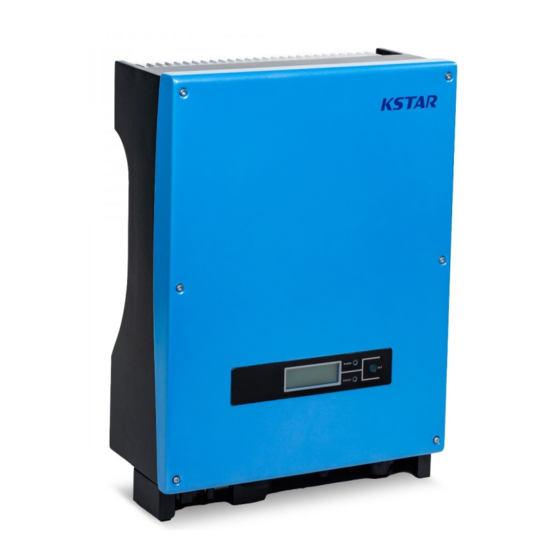
Page 8: Brief Introduction Of Pv Inverter
4.2 Brief Introduction of PV Inverter The inverter coverts DC current from solar units into AC current, and feeds to Municipal Electrical Grid. The inverter is designed and produced as per relative requirement of laws and regulations. The shape and functions of relative parts is described as follows: 1.LCD display panel 6.AC output port 2.LED... -
Page 9: Features Description
3.DC input ports: Inverters have 2 pairs of DC ports, each pair of input ports have positive (+) and negative (-) connector. Please identify the positive and negative position by refer to “installation” section. 4.DC-Switch. 5 . Waterproof air valve : To balance the internal and external atmosphere. -
Page 10: Installation
5 Installation 5.1 Packing Please check carefully before opening the package of the equipment. It may cause the inverter damage in case the packing material is found damage, please contact with forwarder for claim. If necessary, Please feel free to contact us. 5.2 Installation of Inverter Please read the following installation instruction before you start your work so as to achieve best effect of the inverter. -
Page 11: Installation Location
5.3 Installation Location 1. The inverter is suitable to be installed on vertical wall as shown above.. 2. Don’t install inverter on forward tilt wall. 3. Don’t install inverter on horizontal wall. 4. Mount the inverter at height same as eyesight for easy operation and data reading. - Page 12 2. Clean the dust inside the holes, and insert expansion pipe into the holes. And then tighten 4 screws into upper four pipes. 3. Hang the inverter onto the 4 tapping screws, and check both sides and keep the inverter in right position, then tighten two screws as shown in following pictures.
-
Page 13: Wiring
5.5 Wiring Remove wiring cover in the inverter, you will see below shown connection ports: DC Input DC-Switch RS-485 AC Output Dry Contact RS-232 Connector for DC input, the polarity sequence is negative, Input negative, positive, positive (-,-,+,+). Please find label with polarity markers. - Page 14 Input and output cable shall be PV private cables suitable for outdoor use. Table: Miniature circuit breakers specifications DC input AC output Model Recommended DC Recommended AC KSG-3.2K-DM 800V/16A KSG-3.6K-DM 800V/16A KSG-4K-DM 800V/16A KSG-4.6K-DM 800V/16A Installation and Operation Manual...
-
Page 15: Connection Procedure
DC input AC output Model Recommended DC Recommended AC KSG-5K-DM 800V/16A Table: Wiring cable specifications DC input AC output Model Recommended AC Recommended DC cable KSG-3.2K-DM 2.5mm -4mm 2.5mm -6mm KSG-3.6K-DM 2.5mm -4mm -6mm KSG-4K-DM 2.5mm -4mm -6mm KSG-4.6K-DM 2.5mm... -
Page 16: Operation Of Grid-Connected Inverter
6 Operation of Grid-connected Inverter Working LED System Info Model: XXXXX XXXXX XXXXX XXXXX XXXXX Presss button DSP: V1.0 ARM:V1.1 SN: XXXXXXXXXXXX Error LED Installation and Operation Manual... -
Page 17: Trial Operation
6.1 Trial Operation The inverter can be activated only after the following inspections are well executed: 1. Correct connection for AC cables. 2. All solar arrays are connected with the inverter correctly. 3. Tighten all screws. 4. Turn on the breaker between DC and AC. 5. - Page 18 The following example shows the process when PV voltage is increased from 120V: Turn on the inverter, its model and version will be displayed first. System Info Model: XXXXXX DSP: V1.0 ARM: V1.1 SN: XXXXXXXXXXXX The input voltage is less 150V but higher than 120V, Standby the inverter will be in stand-...
-
Page 19: Led Display
2. Fault Status Inverter is always under intelligent monitoring condition after it gets started. It will become faulty status when any fault occurs (such as municipal voltage is overload, frequency is over range) or components failure. The faulty information can be displayed by LCD, at that time the red LED is on. -
Page 20: Lcd Display
6.4 LCD Display 1. Button and Back Lighting Operation There are two types of button press, short time press means pressing the button less than 0.5 second, and long time press means pressing the button more than 1 seconds. The short time press is used for page up, moving the cursor;... - Page 21 If there is long time button press happened when the display stays in some page, then this page of display will be locked. In the same way, long time button press can make a page of display switch between lock and unlock status. The LCD display will return to the first page “Power &...
- Page 22 ● Grid Specification Setting Sub Menu Attention : : : : Please check the LOCAL of inverter grid specification (Table9.2) whether meet the actual requirement and reset if not ! Grid SPEC 1.China 2.Germany 3.Australia Grid SPEC S h o r t t i m e b u t t o n p r e s s move the cursor, and long 4.ltaly time button press select this...
- Page 23 Vpv Start Input: 150 ● Run Setting Sub Menu Unit: Range: 150→ → → → 450 Start Voltage Setting Run Setting Delay Start Input: 1.Vpv Start Unit: 2.Delay Start Range: 20→ → → → 300 3.Vac Min Start Time Setting Vac Min Input: Unit:...
- Page 24 ● Wifi Reset Sub Menu Power Factor Input: 0.000 Range: 0.80→ → → → 1.20 Power Factor Setting Run Setting Power Limit 7.Power Factor Input: Unit: ﹪ ﹪ ﹪ ﹪ 8.Power Limit Range: 0→ → → → 100 9.React Power Power Limit Setting React Power...
- Page 25 ● 485 Address Setting Sub Menu Short time button press setting COMM Address the number of this bit and long time button press change to next bit. ● 485 Protocol Setting Sub Menu 485 Protocol 1.Factory 2.Modbus ● Record Operation Sub Menu Inquiry Record 2:F00-1(500) Grid Volt Low...
- Page 26 ●Statistic Sub Menu Time Statistic Run: Grid: Unit: Hour Run Time and Grid Time Statistic Connected Time 1.Time Statistic Times: 2.Connected Times 3.Peak Power Inverter Normal Work Times Peak Power History: 5289 Today: 2090 Unit: History and Today Peak Power E-Today Num: Unit:...
- Page 27 E-Year Num: Unit: Statistic Yearly Electricity 7.E-Year 8.E-Total E-Total Num: 1342 Unit: ●Date/Time Sub Menu Total Power Generation Date/Time Data: 05/20/2000 Time: 21:03:46 Week:6 ●Burn Mode Sub Menu S h o r t t i m e b u t t o n p r e s s Burn Mode move the cursor, and long 1.Disable...
- Page 28 ●Factory Reset Sub Menu Factory Reset 1.RESET 4. Identification of LCD Display Information Message display Working Conditions Description in English Normal working status Not Functioning Period No display PV voltage < 70V, the inverter is switched off Stand-by Stand-by 120V< PV voltage <150V PV voltage >...
- Page 29 Inverter DCI Over Inverter DC current is too high. Ambient temperature is too High. Amb Temperatur Over Sink Temperatur Over Heatsink temperature is too High. AC Relay Fault AC relay is abnormal. One of PV input is idle when inverter is set PV Loss Fault on parallel mode.
-
Page 30: Max Power Point Tracking (Mppt)
6.5 Max Power Point Tracking (MPPT) Under any arrays or any conditions, the system can be rapidly tracked the max. power from the arrays. When the output power is trending to be stable, which expresses that the inverter reach its Max power, meanwhile maximum power will be received and transferred into AC to feed to municipal electricity Grid by the inverter. -
Page 31: Communication Interface
7 Communication Interface This product provides RS232 and RS485 communication modes, WLAN communication optional. 7.1 RS232 There is water proof RS232 (DB9 type) communication port. Please open the water proof cover before using RS232 port. RS232 port is only used for the online upgrade of the inverter software, the connection between inverter and the computer should be less 15M. -
Page 32: Dry Contact
Pin corresponding relationship between inverter and GPRS/ Wifi unit. 7.3 Dry Contact Dry contact is two terminals of a relay. Relay closes when low insulation or grounding error is detected. Customer can use this to generate audible or visual alarm. Max transfer voltage of the relay is 250Vac/0.25A or 125Vac/0.5A or 30Vdc/2A Dry Contact 7.4 Remote control... -
Page 33: Trouble Shooting
8 Trouble Shooting It is very easy for the inverter’s maintenance. When you meet any problems, please refer to the following trouble shooting first, please contact your local distributor if the problem can’t be solved by yourself. The following sheet lists some basic questions may encounter in the operation. - Page 34 Inverter Current Disconnect PV input and restart the inverter after few minutes and check whether fault still exists. High (F10) Contact with your local distributor if the fault still exists. Inverter DC Disconnect PV input and restart the inverter after few Current high (F11) minutes and check whether fault still exists.
- Page 35 Consistency Disconnect PV input and restart the inverter and check Frequency Fault whether fault still exists. (F23) Contact with your local distributor if the fault still exists. DSP Operation Disconnect PV input and restart the inverter and check whether fault still exists. Fault(F24) Contact with your local distributor if the fault still exists.
-
Page 36: Specification
9 Specification Table 9.1 Technical Data KSG-3.2K KSG-3.6K KSG-4K KSG-4.6K KSG-5K Model DC-Input Parameters Max. Input Power (W) 3300 3800 4200 5200 5200 Max. Input Voltage (Vdc) MPPT Operating Range 100-490 (Vdc) Max.input current per MPPT tracker (A) Rated Input Voltage (Vdc) Numbers of Input MPPT Channel AC-Output Parameters... - Page 37 Altitude (m) ≤2000 Ventilation natural cooling Consumption During <0.2 Night Time (W) Noise (dB) <25 Communication 4 lines characters display, the content can be exchanged by pressing button Communication Interface RS232 & RS485 Mechanical Parameters Dimensions (W×D×H) 329×149×466 Weight (Kg) 14.7 15.1 15.1...
- Page 38 Table 9.3 Model KSG-3.2K-DM KSG-3.6K-DM KSG-4K-DM KSG-4.6K-DM KSG-5K-DM Vmax PV (Vdc) Isc PV (Adc) 2 x 13.2 2 x 15.6 2 x 15.6 2 x 15.6 2 x 15.6 Max. continuous 2 x 11 2 x 13 2 x 13...
Need help?
Do you have a question about the KSG-3.2K-DM and is the answer not in the manual?
Questions and answers