Table of Contents
Advertisement
USER'S MANUAL
Model No. PETL59910.0
Serial No.
Write the serial number in the space
above for future reference.
Serial
Number
Decal
QUESTIONS?
If you have questions, or if there are
missing parts, please contact us:
UK
Call: 08457 089 009
From Ireland: 053 92 36102
Website: www.iconsupport.eu
Write:
ICON Health & Fitness, Ltd.
c/o HI Group PLC, Express Way
Whitwood, West Yorkshire
WF10 5QJ
UK
AUSTRALIA
Call: 1-800-237-173
E-mail:
australiacc@iconfitness.com
CAUTION
Read all precautions and instruc-
tions in this manual before using
this equipment. Save this manual
for future reference.
www.iconeurope.com
Advertisement
Table of Contents

Related Manuals for Pro-Form 500 ZLT PETL59910.0


Summary of Contents for Pro-Form 500 ZLT PETL59910.0
- Page 1 USER'S MANUAL Model No. PETL59910.0 Serial No. Write the serial number in the space above for future reference. Serial Number Decal QUESTIONS? If you have questions, or if there are missing parts, please contact us: Call: 08457 089 009 From Ireland: 053 92 36102 Website: www.iconsupport.eu Write: ICON Health &...
-
Page 2: Table Of Contents
TABLE OF CONTENTS WARNING DECAL PLACEMENT ............. .2 IMPORTANT PRECAUTIONS . -
Page 3: Important Precautions
IMPORTANT PRECAUTIONS WARNING: To reduce the risk of serious injury, read all important precautions and in- structions in this manual and all warnings on your treadmill before using your treadmill. ICON as- sumes no responsibility for personal injury or property damage sustained by or through the use of this product. - Page 4 18. Never leave the treadmill unattended while it 22. Inspect and properly tighten all parts of the is running. Always remove the key, unplug treadmill regularly. DANGER: the power cord, and press the power switch into the off position when the treadmill is not Always unplug the power in use.
-
Page 5: Before You Begin
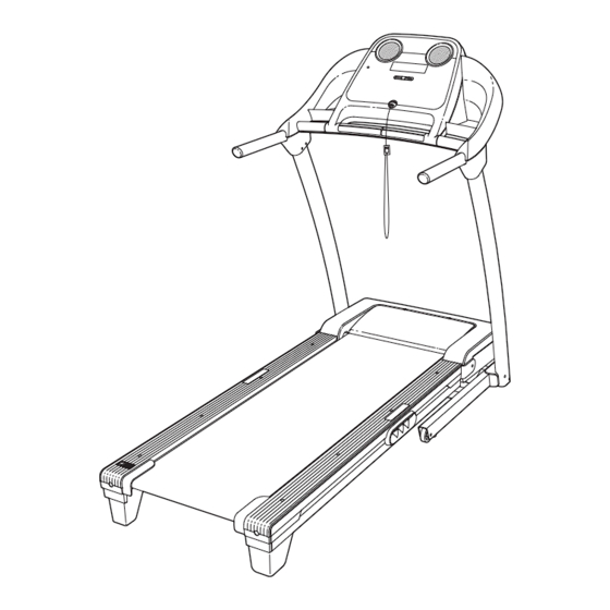
BEFORE YOU BEGIN Thank you for selecting the new PROFORM 500 ZLT ing this manual, please see the front cover of this man- ® treadmill. The 500 ZLT treadmill offers a selection of ual. To help us assist you, note the product model features designed to make your workouts at home more number and serial number before contacting us. -
Page 6: Assembly
ASSEMBLY Assembly requires two persons. Set the treadmill in a cleared area and remove all packing materials. Do not dispose of the packing materials until assembly is completed. Note: The underside of the treadmill walking belt is coated with high-performance lubricant. During shipping, some lubricant may be transferred to the top of the walking belt or the shipping carton. -
Page 7: Frame (56) So That The Treadmill Is More Stable
1. Make sure that the power cord is unplugged. Remove the M10 Nut (19), the M10 x 50mm Bolt (31), and the shipping bracket (A) from the Base (95). Remove the shipping bracket from the other side of the treadmill. Discard the shipping brackets. - Page 8 3. Attach a Wheel (97) with the M10 Nut (19), and the M10 x 50mm Bolt (31) that you removed in step 1. Do not overtighten the Nut; the Wheel must turn freely. Press a Base Cap (87) into the Base (95). 4.
-
Page 9: The Treadmill Onto Its Right Side. Partially Fold The
5. Hold a Bolt Spacer (90) inside the lower end of the Right Upright (89). Insert an M10 x 95mm Patch Bolt (8) with an M10 Star Washer (9) into the Right Upright and the Bolt Spacer. Repeat this step with a second Bolt Spacer (90), an M10 x 68mm Patch Bolt (114), and an M10 Star Washer (9). - Page 10 7. With the help of a second person, hold a Bolt Spacer (90) inside the lower end of the Left Upright (85). Insert an M10 x 95mm Patch Bolt (8) with an M10 Star Washer (9) into the Left Upright and the Bolt Spacer.
- Page 11 9. Set the console assembly face down on a soft surface to avoid scratching the console. Loosen the four #8 x 1" Screws (107). Carefully pivot the Console Frame (111) to the position shown. Do not pivot the Console Frame too far or you will break the ground wire.
- Page 12 11. Have a second person hold the console assem- bly near the Right Upright (89). Console Assembly Connect the Upright Wire (88) to the console wire. See the inset drawing. The connectors should slide together easily and snap into place. If they do not, turn one connector and try again.
- Page 13 13. Slide the Right Upright Cover (110) up against the Right Handrail (101). Attach the Right Upright Cover with two M4 x 16mm Screws (124). Be careful not to overtighten the Screws. Attach the Left Upright Cover (not shown) as de- scribed above.
- Page 14 If you purchase the optional chest pulse sensor (see page 23), follow the steps below to install the re- ceiver included with the chest pulse sensor. 1. Make sure that the power cord is unplugged. Console Remove the five M4 x 19mm Screws (35) and Assembly the two M4 x 45mm Screws (2) from the back of the console assembly.
-
Page 15: Operation And Adjustment
OPERATION AND ADJUSTMENT THE PRE-LUBRICATED WALKING BELT 2. If you are plugging in the power cord in Australia, go to step 3. Your treadmill features a walking belt coated with high- performance lubricant. IMPORTANT: Never apply sil- If you are plugging in the power cord in the UK, icone spray or other substances to the walking belt first press the pins on the power cord into the metal or the walking platform. - Page 16 CONSOLE DIAGRAM Clip FEATURES OF THE CONSOLE purchase iFit cards at any time, go to www.iFit.com or call the telephone number on the front cover of this manual. iFit cards are also available at select The treadmill console offers an impressive array of stores.
- Page 17 HOW TO TURN ON THE POWER HOW TO USE THE MANUAL MODE IMPORTANT: If the treadmill has been exposed to 1. Insert the key into the console. cold temperatures, allow it to warm to room tem- perature before turning on the power. If you do not See HOW TO TURN ON THE POWER at the left.
- Page 18 5. Change the incline of the treadmill as desired. The lower right dis- play—The lower right To change the incline of the treadmill, press the display can show the Incline increase or decrease button or one of the approximate number of numbered Incline buttons.
- Page 19 7. Measure your heart rate if desired. detected, a heart symbol in the lower right display will flash each time your heart beats, one or two Note: If you use the handgrip pulse sensor and dashes will appear, and then your heart rate will be the optional chest pulse sensor at the same shown.
- Page 20 HOW TO USE A CALORIE WORKOUT height of the flashing segment indicates the Current Segment 1. Insert the key into the console. speed setting for the cur- rent segment. At the end See HOW TO TURN ON THE POWER on page 17. of each segment, a se- ries of tones will sound.
- Page 21 HOW TO USE A PERFORMANCE WORKOUT 4. Select the duration of the workout if desired. 1. Insert the key into the console. If you have selected a performance workout, you can set the duration of the workout to a time be- See HOW TO TURN ON THE POWER on page 17.
- Page 22 HOW TO USE AN IFIT WORKOUT 3. Start the workout. To purchase iFit cards, go to www.iFit.com or call the Press the Start button or the Speed increase but- telephone number on the front cover of this manual. ton to start the workout. A moment after you press iFit cards are also available at select stores.
- Page 23 THE INFORMATION MODE HOW TO USE THE STEREO SOUND SYSTEM The console features an information mode that keeps To play music or audio books through the consoleʼs track of the total distance that the walking belt has stereo speakers, you must connect your MP3 player, moved and the total number of hours that the treadmill CD player, or other personal audio player to the con- has been used.
-
Page 24: How To Fold And Move The Treadmill
HOW TO FOLD AND MOVE THE TREADMILL HOW TO FOLD THE TREADMILL HOW TO MOVE THE TREADMILL To avoid damaging the treadmill, adjust the incline Before moving the treadmill, fold it as described at the to the lowest position before you fold the treadmill. left. -
Page 25: Troubleshooting
TROUBLESHOOTING Most treadmill problems can be solved by following the steps below. Find the symptom that applies, and follow the steps listed. If further assistance is needed, please see the front cover of this manual. PROBLEM: The power does not turn on SOLUTION: a. - Page 26 Remove the three M4.2 x 19mm Hood Screws (12) and carefully pivot the Motor Hood (67) off. Locate the Reed Switch (70) and the Magnet (51) on the left side of the Pulley (53). Turn the Pulley until the Magnet is aligned with the Reed Switch. 1/8 in.
- Page 27 PROBLEM: The walking belt is off-center or slips when walked on SOLUTION: a. If the walking belt is off-center, first remove the key and UNPLUG THE POWER CORD. If the walking belt has shifted to the left, use the hex key to turn the left idler roller bolt clockwise 1/2 of a turn;...
-
Page 28: Exercise Guidelines
EXERCISE GUIDELINES WARNING: Burning Fat—To burn fat effectively, you must exer- cise at a low intensity level for a sustained period of Before beginning this time. During the first few minutes of exercise, your or any exercise program, consult your physi- body uses carbohydrate calories for energy. - Page 29 SUGGESTED STRETCHES The correct form for several basic stretches is shown at the right. Move slowly as you stretch—never bounce. 1. Toe Touch Stretch Stand with your knees bent slightly and slowly bend forward from your hips. Allow your back and shoulders to relax as you reach down toward your toes as far as possible.
-
Page 30: Part List
PART LIST—Model No. PETL59910.0 R0610A To locate the parts listed below, see the EXPLODED DRAWING near the end of this manual. Key No. Qty. Description Key No. Qty. Description M4.2 x 19mm Screw Magnet M4 x 45mm Screw Motor Belt M4.2 x 25mm Tek Screw Drive Roller/Pulley #8 x 1/2"... - Page 31 Key No. Qty. Description Key No. Qty. Description Right Handrail M10 x 68mm Patch Bolt Console Ground Wire M8 Flange Nut Console Base M4 x 13mm Screw Left Accessory Tray Motor Bushing Console Motor Isolator Right Accessory Tray Transformer #8 x 1" Screw Filter M5 x 16mm Bolt Receptacle...
-
Page 32: Exploded Drawing
EXPLODED DRAWING A—Model No. PETL59910.0 R0610A... - Page 33 EXPLODED DRAWING B—Model No. PETL59910.0 R0610A...
- Page 34 EXPLODED DRAWING C—Model No. PETL59910.0 R0610A...
- Page 35 EXPLODED DRAWING D—Model No. PETL59910.0 R0610A...
-
Page 36: Ordering Replacement Parts
ORDERING REPLACEMENT PARTS To order replacement parts, see the front cover of this manual. To help us assist you, please be prepared to pro- vide the following information when contacting us: • the model number and the serial number of the product (see the front cover of this manual) •...
Need help?
Do you have a question about the 500 ZLT PETL59910.0 and is the answer not in the manual?
Questions and answers