Advertisement
Table of Contents
- 1 Table of Contents
- 2 Service Manual
- 3 Technical Changes
- 4 Indoor Unit
- 5 Part Names and Functions
- 6 Remote Controller
- 7 Specification
- 8 Outlines and Dimensions
- 9 Wiring Diagram
- 10 Refrigerant System Diagram
- 11 Service Functions
- 12 Troubleshooting
- 13 Disassembly Instructions
- 14 Parts List
- Download this manual
SPLIT-TYPE, AIR CONDITIONERS
SERVICE MANUAL
Wireless type
Models
MS-A08VD-
MS-A10VD-
MS-A13VD-
Indication of model name
MS-A08VD -
MS-A10VD -
MS-A13VD -
NOTE:
• This service manual describes technical data of indoor units.
• As for outdoor units MU-A08VD -
P1
P1
P1
P1
P1
P1
,MU-A10VD -
P1
P1
CONTENTS
1. TECHNICAL CHANGES ····································2
2. PART NAMES AND FUNCTIONS······················3
3. SPECIFICATION·················································4
4. OUTLINES AND DIMENSIONS ·························5
5. WIRING DIAGRAM ············································6
6. REFRIGERANT SYSTEM DIAGRAM ················6
7. SERVICE FUNCTIONS ······································7
8. TROUBLESHOOTING········································9
9. DISASSEMBLY INSTRUCTIONS ····················18
10. PARTS LIST······················································20
and MU-A13VD -
, refer to the service manual OB397.
P1
No. OB396
TM
Advertisement
Table of Contents
Troubleshooting

Related Manuals for Mitsubishi Electric MS-A08VD-P1


Summary of Contents for Mitsubishi Electric MS-A08VD-P1
-
Page 1: Table Of Contents
SPLIT-TYPE, AIR CONDITIONERS No. OB396 SERVICE MANUAL Wireless type Models MS-A08VD- MS-A10VD- MS-A13VD- CONTENTS 1. TECHNICAL CHANGES ····································2 2. PART NAMES AND FUNCTIONS······················3 3. SPECIFICATION·················································4 4. OUTLINES AND DIMENSIONS ·························5 5. WIRING DIAGRAM ············································6 6. REFRIGERANT SYSTEM DIAGRAM ················6 Indication of model name 7. -
Page 2: Technical Changes
TECHNICAL CHANGES MS-07UV - MS-A08VD - MS-10UV - MS-A10VD - MS-13UV - MS-A13VD - 1. Indoor unit has been changed. • Front panel has been changed. (Grill Flat) • Dimension has been changed. (850Wo278Ho191D 815Wo278Ho244D) 2. Easy clean function has been added. 3. -
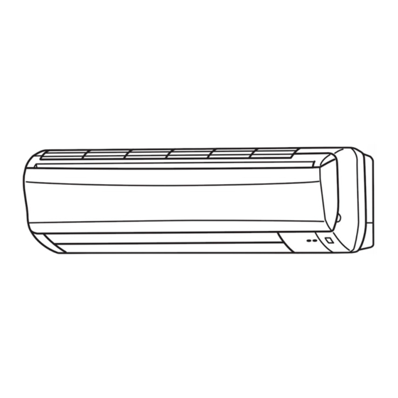
Page 3: Part Names And Functions
PART NAMES AND FUNCTIONS INDOOR UNIT MS-A08VD - MS-A10VD - MS-A13VD - Air cleaning filter (white bellows type) Front panel Air inlet to Breaker Panel Catechin air filter Power supply cord (with deodorizing) Remote control receiving section Air outlet Vertical vanes Remote controller Horizontal vane Operation section... -
Page 4: Specification
REMOTE CONTROLLER MS-A08VD - Signal transmitting section MS-A10VD - MS-A13VD - Operation display section These buttons are able to store the light from nature, fluorescent lamp, etc and ON/OFF shine in the dark. OPERATE/STOP (ON/OFF) button WARM COOL TEMPERATURE buttons ECONO COOL ECONO COOL button I FEEL COOL... -
Page 5: Outlines And Dimensions
OUTLINES AND DIMENSIONS 81.5 133.5 MS-A08VD - Unit : mm Installation plate MS-A10VD - INDOOR UNIT Indoor unit 81.5 81.5 Wall hole Air in Installation plate Liquid line 6.35-0.5m Gas line 9.52-0.43m Insulation 37 O.D 21 I.D Drain hose (Connected part O,D) Insulation Air out 17.5... -
Page 6: Wiring Diagram
WIRING DIAGRAM MS-A08VD - MS-A10VD - MS-A13VD - MODELS WIRING DIAGRAM INDOOR UNIT RT12 TO OUTDOOR RT11 UNIT CN201 CONNECTING 220-230-240V~ NR11 SR141 LD103 CN211 ELECTRONIC CONTROL P.C. BOARD POWER MONITOR, SAFETY RECEIVER POWER DEVICE(FAN) SUPPLY P.C.BOARD CORD REMOTE 220-230-240V CONTROLLER /N 50Hz SYMBOL... -
Page 7: Service Functions
SERVICE FUNCTIONS MS-A08VD - MS-A10VD - MS-A13VD - 7-1. TIMER SHORT MODE For service, set time can be shortened by short circuit of JPG and JPS the electronic control P.C. board. The time will be shortened as follows. (Refer to 8-6.) Set time : 1-minute 1-second Set time : 3-minute... - Page 8 Table 1 1 unit operation 2 units operation 3 units operation 4 units operation No. 1 unit No modification Same as at left Same as at left Same as at left Same as at left Same as at left No. 2 unit –...
-
Page 9: Troubleshooting
TROUBLESHOOTING MS-A08VD - MS-A10VD - MS-A13VD - 8-1. Cautions on troubleshooting 1. Before troubleshooting, check the following: 1) Check the power supply voltage. 2) Check the indoor/outdoor connecting wire for mis-wiring. 2. Take care the following during servicing. 1).Before servicing the air conditioner, be sure to turn off the main unit first with the remote controller, and then after con- firming the horizontal vane is closed, turn off the breaker and / or disconnect the power plug. - Page 10 5. How to install the horizontal vanes If horizontal vanes are not installed correctly, both of the operation indicator lamps will flash. In this case, install the horizontal vanes correctly by following the procedures 1 to 6. NOTE: Before installation of the horizontal vanes, disconnect the power supply plug and/ or turn off the breaker. Upper vane Stopper Stopper...
- Page 11 8-2. Instruction of troubleshooting Start Indoor unit Indoor unit OPERATION INDICATOR operates. doesn't receive lamp on the indoor unit is Outdoor unit the signal from flashing on and off. doesn't remote controller. operate. Outdoor unit Indoor unit Indoor unit doesn't Outdoor unit doesn't operate, operates, when...
- Page 12 8-3. Troubleshooting check table • The following indication applies regardless of shape of the indicator. flashing · Flashing of the OPERATION INDICATOR lamp (on the left) Operation Indicator indicates possible abnormalities. · The OPERATION INDICATOR lamp (on the left) is lighting during normal operation.
- Page 13 8-4. Trouble criterion of main parts MS-A08VD - MS-A10VD - MS-A13VD - Part name Check method and criterion Figure Measure the resistance with a tester. Room temperature (Part temperature 10°C ~ 30°C) thermistor (RT11) Normal Abnormal Indoor coil Open or short-circuit 8k"...
-
Page 14: Troubleshooting Flow
8-5. Troubleshooting flow When left OPERATION INDICATOR lamp flashes 3-time. Indoor fan motor doesn’t operate. A A Check of indoor fan motor Turn OFF the power supply. Check connector CN211 visually. Is soldering point of the connector Are lead wires connected? correctly soldered? Reconnect the lead wires. -
Page 15: Check Of Indoor Electronic Control P.c. Board
The unit doesn’t operate with the remote controller. Also, the OPERATION INDICATOR lamp doesn’t light up by pressing the EMERGENCY OPERATION switch. Check of indoor electronic control P.C. board Check both “parts side” and “pattern side” of the indoor electronic control P.C. board visually. - Page 16 When both OPERATION INDICATOR lamps flash ON and OFF every 0.5-second. Indoor unit and outdoor unit don’t operate. Check of installation of the horizontal vane Start Turn OFF the power supply. Relock the stopper of the Is the stopper of the horizontal vane horizontal vane to the indoor unit.
- Page 17 8-6. Test point diagram and voltage MS-A08VD - MS-A10VD - MS-A13VD - Power supply input 220-230-240V AC Indoor electronic control P.C. board Fuse 250V AC 3.15A Indoor fan motor 220-230-240V AC Varistor (NR12) Safety device of fan by horizontal vane CN1R1 Room temperature Varistor thermistor (RT11)
-
Page 18: Disassembly Instructions
DISASSEMBLY INSTRUCTIONS <"Terminal with locking mechanism" Detaching points> The terminal which has the locking mechanism can be detached as shown below. There are two types ( Refer to (1) and (2)) of the terminal with locking mechanism. The terminal without locking mechanism can be detached by pulling it out. Check the shape of the terminal before detaching. - Page 19 OPERATING PROCEDURE PHOTOS 3. Removing the electrical box Vane motor Photo 3 Indoor coil thermistor (1) Remove the panel. (Refer to 1.) connector connector (2) Remove the electrical cover. (Refer to 2.) (3) Remove the V.A. clamp. (Refer to 2.) Screw of the (4) Remove the cord clamp.
-
Page 20: Parts List
PARTS LIST MS-A08VD - MS-A10VD - MS-A13VD - 10-1. INDOOR UNIT STRUCTURAL PARTS 10-2. ACCESSORY AND REMOTE CONTROLLER 7 (See 10-5.) (W) This figure shows MS-A13VD. 10-1. INDOOR UNIT STRUCTURAL PARTS Q'ty/unit Symbol Part No. Remarks Price Part name in Wiring A08VD - A10VD - A13VD -... - Page 21 MS-A08VD - MS-A10VD - MS-A13VD - 10-4. INDOOR UNIT HEAT EXCHANGER 10-3. INDOOR UNIT ELECTRICAL PARTS AND FUNCTIONAL PARTS 22(W) SLEEVE BEARING ROOM TEMPERATURE THERMISTOR (W) This figure shows MS-A13VD. FUSE VARISTOR 10-3. INDOOR UNIT ELECTRICAL PARTS AND FUNCTIONAL PARTS Part number that is circled is not shown in the illustration.
- Page 22 10-5. AIR CLEANING FILTER AIR CLEANING FILTER removes fine dust of 0.01 micron from air by means of static electricity. Normal life of AIR CLEANING FILTER is 4 months. However, when it becomes dirty, replace it as soon as possible. Clogged AIR CLEANING FILTER may reduce the air conditioner capacity or cause frost on the air outlet.
- Page 24 HEAD OFFICE: MITSUBISHI DENKI BLDG., 2-2-3, MARUNOUCHI, CHIYODA-KU, TOKYO100-8310, JAPAN C C Copyright 2005 MITSUBISHI ELECTRIC ENGINEERING CO.,LTD. New publication, effective Mar. 2005 Distributed in Mar. 2005. No.OB396 106 Specifications subject to change without notice. Made in Japan...
Need help?
Do you have a question about the MS-A08VD-P1 and is the answer not in the manual?
Questions and answers