Advertisement
SPLIT-TYPE AIR CONDITIONERS
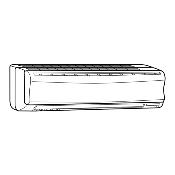
INDOOR UNIT
SERVICE MANUAL
Models
MS-A18VD-
MS-A18VD-
MS-A24VD-
MS-A24VD-
MS-A30VD-
MS-A30VD-
MS-A18VD
MS-A24VD
MS-A30VD
NOTE:
• This service manual describes technical data of the indoor units.
• RoHS compliant products have <G> mark on the spec name plate.
For servicing of RoHS compliant products, refer to the RoHS Parts List.
K1
K2
K1
K2
K1
K2
CONTENTS
1. TECHNICAL CHANGES ····································2
2. PART NAMES AND FUNCTIONS······················3
3. SPECIFICATION·················································5
4. OUTLINES AND DIMENSIONS ·························6
5. WIRING DIAGRAM ············································7
6. REFRIGERANT SYSTEM DIAGRAM ················9
7. SERVICE FUNCTIONS ····································10
8. TROUBLESHOOTING······································12
9. DISASSEMBLY INSTRUCTIONS ····················21
10. PARTS LIST······················································23
11. RoHS PARTS LIST···········································26
Revision C:
• Another type of the electronic control P.C.
board (TYPE 2) has been added to the
original one (TYPE 1). They are both com-
patible with MS-A18/24/30VD-
Please void OB400, REVISED EDITION-B.
No. OB400
REVISED EDITION-C
Outdoor unit service manual
MU-A·VD Series (OB401)
.
K
TM
Advertisement
Table of Contents

Related Manuals for Mitsubishi Electric MS-A18VD-K1


Summary of Contents for Mitsubishi Electric MS-A18VD-K1
-
Page 1: Table Of Contents
Revision C: • Another type of the electronic control P.C. board (TYPE 2) has been added to the original one (TYPE 1). They are both com- SPLIT-TYPE AIR CONDITIONERS patible with MS-A18/24/30VD- Please void OB400, REVISED EDITION-B. INDOOR UNIT No. OB400 SERVICE MANUAL REVISED EDITION-C Models... -
Page 2: Technical Changes
Use the specified refrigerant only Never use any refrigerant other than that specified. Doing so may cause a burst, an explosion, or fire when the unit is being used, serviced, or disposed of. Correct refrigerant is specified in the manuals and on the spec labels provided with our products. We will not be held responsible for mechanical failure, system malfunction, unit breakdown or accidents caused by failure to follow the instructions. -
Page 3: Part Names And Functions
PART NAMES AND FUNCTIONS INDOOR UNIT MS-A18VD MS-A24VD MS-A30VD Air cleaning filter Grille (White bellows type) Air inlet Front Panel Catechin air filter Remote control receiving section Vertical vanes Horizontal vane Remote controller Operation section Display section (When the grille is opened) Operation indicator lamp Emergency operation switch Remote control... - Page 4 ACCESSORIES Installation plate Installation plate fixing screw 4 x 25 mm Remote controller holder Fixing screw for 3 3.5 x 16 mm (Black) Battery (AAA) for remote controller Wireless remote controller Felt tape (Used for left or left-rear piping) Air cleaning filter Pipe cover REMOTE CONTROLLER MS-A18VD...
-
Page 5: Specification
SPECIFICATION Indoor model MS-A18VD - MS-A18VD - MS-A24VD - MS-A24VD - MS-A30VD - MS-A30VD - Cooling Function Single phase Power supply 220-230-240V, 50Hz 774/660/552 Capacity Air flow (High/Med./Low) K /h 972/828/684 Running current 0.30-0.30-0.31 0.33-0.34-0.35 Power input 60-60-64 67-69-75 Auxiliary heater —... -
Page 6: Outlines And Dimensions
OUTLINES AND DIMENSIONS MS-A18VD MS-A24VD MS-A30VD Unit: mm INDOOR UNIT Installation plate Indoor unit 1068 414.5 414.5 Wall hole [75 Liquid line [ 6.35- 0.5m Gas line [ 12-0.43m Insulation [ 50 O.D 1100 Air in [ 32 I.D Installation plate for MS-A18VD for MS-A24VD Liquid line [ 9.52- 0.5m... -
Page 7: Wiring Diagram
WIRING DIAGRAM MS-A18VD - MS-A24VD - INDOOR UNIT RT12 TO OUTDOOR UNIT HIC1 RT11 CN201 CONNECTING 52C/ 220-230-240V~ NR11 220-230-240V~ SR141 CN211 ELECTRONIC CONTROL P.C. BOARD DISPLAY RECEIVER P.C. BOARD P.C. BOARD REMOTE CONTROLLER SYMBOL NAME SYMBOL NAME SYMBOL NAME INDOOR FAN CAPACITOR HORIZONTAL VANE MOTOR SOLID STATE RELAY... - Page 8 MS-A30VD INDOOR UNIT RT13 TO OUTDOOR HIC1 UNIT RT12 CONNECTING CN112 CN201 NR11 SR141 220-230-240V~ TAB12 CN211 ELECTRONIC CONTROL P.C. BOARD RT11 DISPLAY RECEIVER P.C. BOARD P.C. BOARD REMOTE CONTROLLER SYMBOL NAME SYMBOL NAME SYMBOL NAME INDOOR FAN CAPACITOR VERTICAL VANE MOTOR SOLID STATE RELAY SR141 FUSE (T3.15AL250V)
-
Page 9: Refrigerant System Diagram
REFRIGERANT SYSTEM DIAGRAM MS-A18VD Unit : mm INDOOR UNIT Refrigerant pipe [12.7 (with heat insulator) Indoor coil Indoor thermistor heat RT12 exchanger Flared connection Distributor RT11 Room temperature thermistor Strainer Flared connection Refrigerant pipe [6.35 (with heat insulator) MS-A24VD MS-A30VD INDOOR UNIT INDOOR UNIT Refrigerant pipe... -
Page 10: Service Functions
SERVICE FUNCTIONS MS-A18VD MS-A24VD MS-A30VD 7-1. TIMER SHORT MODE For service, set time can be shortened by short circuit of JPG and JPS the electronic control P.C. board. The time will be shortened as follows. (Refer to 8-6.) Set time : 1-minute 1-second Set time : 3-minute 3-second... - Page 11 Table 1 1 unit operation 2 units operation 3 units operation 4 units operation No. 1 unit No modification Same as at left Same as at left Same as at left No. 2 unit – Solder J1 Same as at left Same as at left No.
-
Page 12: Troubleshooting
TROUBLESHOOTING MS-A18VD MS-A24VD MS-A30VD 8-1. Cautions on troubleshooting 1. Before troubleshooting, check the following: 1) Check the power supply voltage. 2) Check the indoor/outdoor connecting wire for mis-wiring. 2. Take care the following during servicing. 1) Before servicing the air conditioner, be sure to turn off the unit first with the remote controller, and then after confirm- ing the horizontal vane is closed, turn off the breaker and / or disconnect the power plug. - Page 13 8-2. Instruction of troubleshooting Start Indoor unit Indoor unit Indoor unit operates. OPERATION INDICATOR operates. does not receive Outdoor unit lamp on the indoor unit is Outdoor unit the signal from does not operate flashing on and off. does not remote controller.
- Page 14 8-3. Troubleshooting check table • Before taking measures, make sure that the symptom reappears for accurate troubleshooting. When the indoor unit has started operation and the following detection method has detected an abnormality (the first detection after the power ON), the indoor electronic control P.C. board turns OFF the indoor fan motor with the OPERATION INDICATOR lamp flashing.
- Page 15 8-4. Trouble criterion of main parts MS-A18VD MS-A24VD MS-A30VD Part name Check method and criterion Figure Room Measure the resistance with a tester. temperature (Part temperature 10°C ~ 30°C) thermistor (RT11) Refer to 8-6. “Test point diagram and voltage”, “Indoor electronic control P.C. Indoor coil board”, for the chart of thermistor.
- Page 16 8-5. Troubleshooting flow When OPERATION INDICATOR lamp flashes 3-time. Indoor fan motor does not operate. Turn OFF the power supply. A A Check of indoor fan motor Check connector CN211 visually. Is soldered point of the connector Are lead wires connected? correctly soldered? Reconnect the lead wires.
- Page 17 The unit does not operate with the remote controller. Also, the OPERATION INDICATOR lamp does not light up by pressing the EMERGENCY OPERATION switch. Check of indoor electronic control P.C. board Check both “parts side” and “pattern side” of the indoor electronic control P.C. board visually.
- Page 18 When OPERATION INDICATOR lamp flashes ON and OFF in every 0.5-second. Outdoor unit does not operate. How to check mis-wiring MS-A30VD w Short circuit of JPG and JPS on the indoor electronic control P.C. board enables self-check to be displayed in 3 seconds. Start •...
- Page 19 8-6. Test point diagram and voltage w There are 2 types of electronic control P.C. boards MS-A18VD MS-A24VD MS-A30VD (TYPE1/TYPE2). Indoor electronic control P.C.board They are both compatible with MS-A18/24/30VD. Varistor (NR11) TYPE 1 Fan motor power supply 220-230-240 VAC(CN211) Power supply input 220-230-240 VAC 5 VDC...
- Page 20 MS-A18VD MS-A24VD MS-A30VD Indoor electronic control P.C.board TYPE 2 Fan motor power supply (CN211) Power supply input 220-230-240 VAC Fuse (F11) T3.15AL250V 5 VDC PS132 MS-A30VD Room temperature thermistor (RT11) Indoor coil thermistor (RT12 (main)) MS-A30VD Indoor coil thermistor (RT13 (sub)) 12 VDC CN121 Vane motor...
-
Page 21: Disassembly Instructions
DISASSEMBLY INSTRUCTIONS <"Terminal with locking mechanism" Detaching points> The terminal which has the locking mechanism can be detached as shown below. There are two types ( Refer to (1) and (2)) of the terminal with locking mechanism. The terminal without locking mechanism can be detached by pulling it out. Check the shape of the terminal before detaching. - Page 22 OPERATING PROCEDURE PHOTOS 3. Removing the electrical box Photo 3 Screws of the ground wire (1) Remove the front panel. (Refer to 1.) (2) Remove the electrical cover. (Refer to 2.) (3) Disconnect the connector of the indoor coil thermistor. (4) Disconnect the motor connector (CN211 and CN121) and the vane motor connector (CN151) on the electronic Screw of the...
-
Page 23: Parts List
PARTS LIST (non-RoHS compliant) MS-A18VD MS-A24VD MS-A30VD 10-2. INDOOR UNIT HEAT EXCHANGER 10-1. INDOOR UNIT STRUCTURAL PARTS CATCH (See 10-5.) SCREW 10-1. INDOOR UNIT STRUCTURAL PARTS Part number that is circled is not shown in the illustration. Q'ty/unit Symbol in Wiring Part No. - Page 24 PARTS LIST (non-RoHS compliant) MS-A18VD MS-A24VD MS-A30VD 10-3. INDOOR UNIT FUNCTIONAL PARTS AND ELECTRICAL PARTS 10-3. INDOOR UNIT FUNCTIONAL PARTS AND ELECTRICAL PARTS Part numbers that are circled are not shown in the illustration. Q'ty/unit Symbol Part No. Part name Remarks in Wiring MS-A18...
- Page 25 PARTS LIST (non-RoHS compliant) MS-A18VD MS-A24VD MS-A30VD 10-4. ACCESSORY AND REMOTE CONTROLLER 10-4. ACCESSORY AND REMOTE CONTROLLER Q'ty/unit Symbol Part No. Part name Remarks in Wiring MS-A18 MS-A18 MS-A24 MS-A24 MS-A30 MS-A30 Diagram E02 527 426 REMOTE CONTROLLER KM04B E02 527 083 REMOTE CONTROLLER HOLDER 10-5.
-
Page 26: Rohs Parts List
RoHS PARTS LIST (RoHS compliant) MS-A18VD MS-A24VD MS-A30VD 11-2. INDOOR UNIT HEAT EXCHANGER 11-1. INDOOR UNIT STRUCTURAL PARTS CATCH (See 11-5.) SCREW 11-1. INDOOR UNIT STRUCTURAL PARTS Part number that is circled is not shown in the illustration. Q'ty/unit Symbol in Wiring Part No. - Page 27 RoHS PARTS LIST (RoHS compliant) MS-A18VD MS-A24VD MS-A30VD 11-3. INDOOR UNIT FUNCTIONAL PARTS AND ELECTRICAL PARTS 11-3. INDOOR UNIT FUNCTIONAL PARTS AND ELECTRICAL PARTS Part numbers that are circled are not shown in the illustration. Q'ty/unit Symbol Part No. Part name Remarks in Wiring MS-A18...
- Page 28 MS-A30VD - MS-A30VD - HEAD OFFICE: TOKYO BLDG., 2-7-3, MARUNOUCHI, CHIYODA-KU, TOKYO 100-8310, JAPAN C C Copyright 2005 MITSUBISHI ELECTRIC ENGINEERING CO.,LTD Distributed in Aug. 2011. No.OB400 REVISED EDITION-C Distributed in May 2006. No.OB400 REVISED EDITION-B 6 Distributed in Nov. 2005. No.OB400 REVISED EDITION-A 6 Distributed in Mar.
Need help?
Do you have a question about the MS-A18VD-K1 and is the answer not in the manual?
Questions and answers