L-Acoustics LA8 User Manual
Amplified controller
Hide thumbs
Also See for LA8:
- User manual (92 pages) ,
- Maintenance manual (21 pages) ,
- Product information (21 pages)

Related Manuals for L-Acoustics LA8


Summary of Contents for L-Acoustics LA8
- Page 1 LA8 AMPLIFIED CONTROLLER USER MANUAL VERS ION 5.0 w w w . l - a c ou s ti c s . c om...
-
Page 2: Safety Instructions
Mains supply Only connect the LA8 (CE type) or LA8US (US type) to an AC power outlet rated 230 V, 16 A, 50 - 60 Hz or 120 V, 30 A, 50-60 Hz. Only connect the LA8JP (Japan model) to an AC power outlet rated 100 V, 30 A, 50 - 60 Hz or 200 V, 15 A, 50- 60 Hz. - Page 3 Do not attempt to service this product as removing covers may expose to dangerous voltage or other hazards. The use of unauthorized replacement parts may result in injury and/or damage through fire, electric shock, or other electricity-related hazards. All service and repair work must be carried out by an L-ACOUSTICS ® authorized dealer.
- Page 4 LA8 AMPLIFIED CONTROLLER USER MANUAL VERS ION 5.0 SYMBOLS INDICATED ON THE PRODUCT The product is potentially life threatening if open. Never attempt to remove the back cover. The lightning flashes symbols next to the SpeakON ® and CA- ®...
-
Page 5: Table Of Contents
LA8 amplified controller. This document contains essential information on using the product properly. Carefully read this document in order to become familiar with these procedures. As part of a continuous evolution of techniques and standards, L-ACOUSTICS ® reserves the right to change the specifications of its products and the content of its documents without prior notice. - Page 6 LA8 AMPLIFIED CONTROLLER USER MANUAL VERS ION 5.0 3.3.7 Example of heat power calculation......................16 Audio a nd network cabling ............................17 3.4.1 Connection pa nels ............................17 3.4.2 Analog audio cabling ............................17 3.4.3 AES/EBU digital audio cabling ........................18 3.4.4 Loudspeaker cabling ............................20 3.4.5...
-
Page 7: Integrated System Approach
The LA4 delivers up to 4 x 1000 watt into 4 ohm. The LA8 delivers up to 4 x 1800 watt into 4 or 2.7 ohm. An AES/EBU input card is integrated to the LA8 for digital audio implementation. This feature is available as an option on the LA4. -
Page 8: System Components
Powering and driving systems Amplified controller with DSP library and networking capabilities. LA-RAK Touring rack containing three LA8, for power, audio signals and network distribution. 1.3.2 Loudspeaker enclosures and cables Refer to the user manuals of the loudspeaker systems for detailed instructions about the enclosures and their connection to the LA amplified controllers. -
Page 9: La8 Amplified Controller
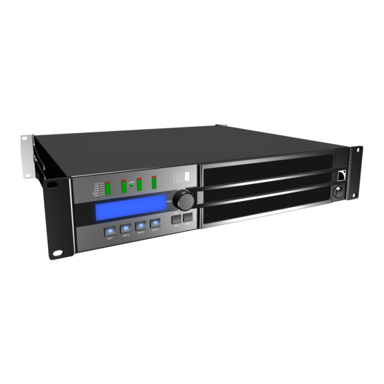
LA8 AMPLIFIED CONTROLLER Main features 2.1.1 Front and rear panels Figure 2: LA8 front and rear panels LED meters: input selection/menu keys CLIP level output selection keys audio level (-25, -10, -5 dB) SIGNAL presence analog audio IN/LINK connectors (XLR) -
Page 10: Simplified Block Diagram
Simplified block diagram The core of the LA8 is a DSP engine driving four channels of amplification from two inputs. The LA8 also features a flash memory for preset storage and management, high performance A/D-D/A converters for audio signals, an auto- sensing SMPS (Switched Mode Power Supply), a front panel user interface, and a Fast Ethernet device for network remote control. -
Page 11: Signal Processing And Amplification
XLR3 male connector. To be processed by the DSP, the analog signal needs to be converted into a digital signal. For this purpose, the LA8 amplified controller is fitted with two cascaded 24-bit A/D converters with a sampling rate of 96 kHz allowing an encoding dynamic range of 130 dB. -
Page 12: Dsp Architecture
With a complete factory preset library and the possibility of creating additional user presets, the flash memory offers a quick access to all the usual L-ACOUSTICS ® speaker system configurations (refer to the PRESET GUIDE). -
Page 13: Amplifier Section And Power Supply
The design of complex systems is made possible by the integration of the L -NET Ethernet-based network. Thanks to its high speed data transfer protocol of 100 Mbit/sec, up to 253 units (LA4 and LA8) can be controlled and monitored in real-time from LA NETWORK MANAGER software. -
Page 14: Installation
Mounting The LA8 is two rack units high (2U) and can be mounted in an EIA-standard 19’’ rack (see Figure 5). The four points on the front panel are for rack mounting. Use four screws and washers to mount the controller to the rack front rails. -
Page 15: Cooling
3.3.1 AC mains specifications Only connect the LA8 (CE type) or LA8US (US type) to an AC power outlet rated 230 V, 16 A, 50 - 60 Hz or 120 V, 30 A, 50-60 Hz. Only connect the LA8JP (Japan type) to an AC power outlet rated 100 V, 30 A, 50 - 60 Hz or 200 V, 15 A, 50-60 To plug the controller to a mains only use an outlet fitted with a pin tied to ground. -
Page 16: Electrical Generator
Then apply the following formula: I x U / (cos x range). For instance, for LA8 in Europe, I = 16 A and U = 230 V. With a typical generator, cos = 0.8 and range = 70 %. -
Page 17: Audio And Network Cabling
Analog audio cabling The analog XLR connectors on the LA8 are wired according to IEC 268: pin 1= shield, pin 2= + signal, pin 3= - signal. Two 3-point female XLR input connectors (IN A and IN B) are provided for the LA8 to receive two analog signals. -
Page 18: Aes/Ebu Digital Audio Cabling
AES/EBU digital audio cabling Both AES/EBU XLR connectors on the LA8 are transformer balanced and wired a ccording to IEC 268. The 3-point female XLR input connector (IN) is provided for the amplifier to receive one AES/EBU (AES3) or coaxial S/PDIF (IEC 60958 Type II) signal. - Page 19 Figure 10: Daisy-chaining digital audio Figure 11: Digital input panel wiring w w w . l - a c o u s t i c s . c o m LA 8_U M_E N_5 .0...
-
Page 20: Loudspeaker Cabling
® ® All other L-ACOUSTICS PA-COM cables can be used. Refer to the LA8 PACOM CABLES technical bulletin for more details. Loudspeaker system connection Before connecting a loudspeaker system refer to the applicable user manuals for further instructions. ® ®... -
Page 21: L-Net Cabling
The LA8 can be remote controlled over an Ethernet network (called L-NET) using LA NETWORK MANAGER software (refer to the LA NETWORK MANAGER video tutorial). To connect the LA8 to L-NET use the Ethernet RJ45 connectors on the LA8 rear panel (see Figure 7). -
Page 22: Operation
Standby Mode will be displayed on the LCD screen while the controller is in standby mode. It is possible to cancel the standby mode from LA NETWORK MANAGER or from the LA8 front panel interface ( push and hold the encoder wheel for one second). -
Page 23: Display
Display 4.2.1 Main screen Once the start-up sequence has fully cycled (refer to section 4.1), the LCD displays the main screen: Figure 15: Main screen Preset memory number (1 to 255) Memory space containing the current preset. The preset can be a user preset or come from an on-board preset library (refer to section 4.4). Preset name Copied from a preset library or entered by the user (if prior stored as a user preset). -
Page 24: Led Meters
4.2.3 L-NET LED The L-NET LED is lit in green (see Figure 17) when the LA8 is part of a network of controllers and driven by LA NETWORK MANAGER software (refer to the LA NETWORK MANAGER video tutorial). Front panel commands The front panel commands remain accessible if the L-NET LED is lit. -
Page 25: User Interface
User interface 4.3.1 Quick access The LA8 offers quick access functions for control (front panel locking, mute, and gain), identification and monitoring (display of the selected input mode, input level, routing, and group name). Lock/Unlock control To lock the front panel (even the mute function) and prevent unintentional operation press and hold the IN A and IN B keys simultaneously until Display Locked is displayed on the LCD screen. - Page 26 LA8 AMPLIFIED CONTROLLER USER MANUAL VERS ION 5.0 Identification If the controller is online with LA NETWORK MANAGER, it can be identified among other units in the workspace (refer to the LA NETWORK MANAGER video tutorial). Press and hold the encoder wheel from the main screen to launch the Identification function.
- Page 27 Figure 22: Pressing IN A or IN B Input voltage values The SIGNAL LED is lit when the input voltage reaches -37.8 dBu (analog audio source) or -59.8 dBfs (digital audio source). The CLIP LED is lit when the input voltage reaches 22 dBu (analog audio source) or -0.1 dBfs (digital audio source).
-
Page 28: Main Menu
RMS output voltage measured in real-time at each output channel OPTIONS display the MAC address of the LA8 as well as firmware version and current preset version reset all parameters to factory defaults To select a menu page follow these steps (see also Figure 23): Press and release the encoder wheel. -
Page 29: Load Preset
Contents LOAD PST USER 1 – 10 (read and write) User presets stored by the user (refer to section 4.5). Factory preset library created by L-ACOUSTICS ® LOAD PST FACTORY 11 – 199 (read only) automatically installed during firmware update (refer to the LA NETWORK MANAGER video tutorial). -
Page 30: Store Preset
LA8 AMPLIFIED CONTROLLER USER MANUAL VERS ION 5.0 STORE PRESET The current preset and the possible setting modifications can be stored to a user memory (1-10). Modifications flag The modifications of the preset parameters are indicated by a star sign (on the top right corner of the LCD screen) until the preset has been stored to a user memory or set to its initial settings. -
Page 31: Delete Preset
DELETE PRESET A user preset contained in a user memory (1-10) can be deleted following these steps (see also Figure 26): From the main menu select DELETE PRESET. If the controller displays NO PRESETS AVAILABLE! it means that all user memories are empty. Press the ESC key to abort. -
Page 32: Preset Parameters
LA8 AMPLIFIED CONTROLLER USER MANUAL VERS ION 5.0 PRESET PARAMETERS The preset parameters (gain, delay, polarity, and routing) of the current preset can be set individually for each output channel or channel set (see the following INFORMATION note). Channel set In certain presets, some channels are interdependent and form what is called a channel set. -
Page 33: Clear Group Parameters
Therefore, when getting a controller for a standalone application that has been previously used within a network, L-ACOUSTICS ® recommends using the CLEAR GRP PARAM function to clear all group parameters as they cannot be seen and accessed via the front panel user interface. -
Page 34: Options
LA8 AMPLIFIED CONTROLLER USER MANUAL VERS ION 5.0 OPTIONS OPTIONS is a control and monitoring menu allowing to: Set the amplified controller IP address, input mode (analog or AES/EBU as well as fallback options), delay unit (ms, meters, feet, or samples), and LCD screen contrast. -
Page 35: Network Address
NETWORK ADDRESS Remote control of LA4 and LA8 requires setting up a private local area Ethernet network to interconnect up to 253 units with a single control computer (and possible additional devices such as Ethernet switches). It is called L -NET and uses a proprietary communication protocol based on TCP/IPv4 called L-COM. -
Page 36: Input Mode
LA8 AMPLIFIED CONTROLLER USER MANUAL VERS ION 5.0 4.9.2 INPUT MODE This function allows selecting the physical input connector according to the audio source feeding the amplified controller: An analog audio source connects to the IN A and/or IN B inputs of the ANALOG panel (see Figure 7). - Page 37 Sound cut can be avoided using the FALLBACK MODE (refer to section 4.9.3) and a backup analog audio source. In case of UNLOCK status the ANALOG inputs will automatically be selected, leading to one of the screens of Figure 33. AN.FBACK indicates that the amplified controller has switched from AES/EBU to ANALOG inputs.
-
Page 38: Fallback Mode
LA8 AMPLIFIED CONTROLLER USER MANUAL VERS ION 5.0 4.9.3 FALLBACK MODE An automatic fallback option can be enabled or disabled. When enabled, and when the AES/EBU input mode is selected, this option prevents sound cut in case of digital signal failure (no clock, loss of lock, invalid audio [validity bit], CRC error, bipolar encoding error, data slip) since the controller will automatically switch from the AES/EBU input to the analog inputs. -
Page 39: Aes/Ebu In Gain
4.9.4 AES/EBU IN GAIN The LA-AES3 card includes an input gain module which can be set from -12 dB to +12 dB by 0.1 dB steps. It helps aligning the digital audio source level to the analog level value so as to ensure seamless fallback switch from AES/EBU to analog inputs in case of fallback mode activation (refer to section 4.9.3). -
Page 40: Spk Handling
The start-up sequence is launched (refer to section 4.1). When complete, the main screen is displayed with the default preset memory (011) and IP address (100), indicating that the LA8 has returned to its factory default settings and all user memories have been deleted. -
Page 41: Appendix A: Protection Systems
The LA8 amplified controller uses an auto-sensing SMPS (Switched Mode Power Supply) compatible with mains input nominal voltages of 120 / 230 V ±10 % (LA8, LA8US) or 100/200 V ±10 % (LA8JP). The mains voltage is continuously monitored for under and over-voltage as well as for failure in alternating cycles. - Page 42 Error, see the figure on the right. For safety reasons all other channels are also disabled. The controller must be sent to an L-ACOUSTICS ® representative for maintenance.
-
Page 43: Appendix B: Approvals
EN60065: Safety requirements for audio, video and similar electronic apparatus. EN55103-1: Electromagnetic Interference (Emission). EN55103-2: Electromagnetic Susceptibility (Immunity). Additional approvals The LA8 amplified controller has been CB, CCC, and cTUVus certified. It also complies with EMC and RoHS directives . The main standards tested were: Safety requirements:... -
Page 44: Appendix C: Specifications
LA8 AMPLIFIED CONTROLLER USER MANUAL VERS ION 5.0 APPENDIX C: SPECIFICATIONS GENERAL Output power 8 Ω 4 x 1100 W RMS 4 x 1300 W peak EIA (1% THD, 1 kHz, all channels driven) 4 or 2.7 Ω 4 x 1800 W RMS... - Page 45 ANALOG INPUT ® Input 2 Neutrik female XLR3, IEC 268, ESD protected Connectors Link 2 Neutrik ® male XLR3, IEC 268, ESD protected Input 22 kΩ (balanced) impedance Max input level 22 dBu (balanced, THD 1 %) Latency 3.9 ms Digital two cascaded 24 bit A/D converters (130 dB dynamic range) conversion...
- Page 46 LA8 AMPLIFIED CONTROLLER USER MANUAL VERS ION 5.0 w w w . l - a c o u s t i c s . c o m LA 8_U M_E N_5 .0...
- Page 47 w w w . l - a c o u s t i c s . c o m LA 8_U M_E N_5 .0...
- Page 48 Distribution date: March 4 , 2013 ® © 2013 L-ACOUSTICS . All rights reserved. No part of this publication may be reproduced or transmitted in any form or by any means without the express written consent of the publisher. w w w . l - a c ou s ti c s . c om...
Need help?
Do you have a question about the LA8 and is the answer not in the manual?
Questions and answers