Sargent and Greenleaf 6124 Installation Instructions Manual
Motorized electronic
combination lock
Hide thumbs
Also See for 6124:
- Set up and operation manual (19 pages) ,
- Management manual (5 pages) ,
- Operating instructions (2 pages)
Advertisement
Quick Links
6124/6126
Motorized Electronic
Combination Lock
This Sargent & Greenleaf 6100 series electronic lock combines ease of operation with security.
Advanced electronic circuit design makes it easy to install, easy to open, and easy to change
codes. Follow these instructions carefully to get the best possible performance from your lock.
M
C
OUNTING
ONSIDERATIONS
• Sargent & Greenleaf 6100 series Motorized Electronic Combination Locks have been designed to
use the same mounting screw locations and occupy the same space as a standard S&G 6730
mechanical lock. The 6100 series uses standard mounting dimensions to
simplify retrofit in existing safes.
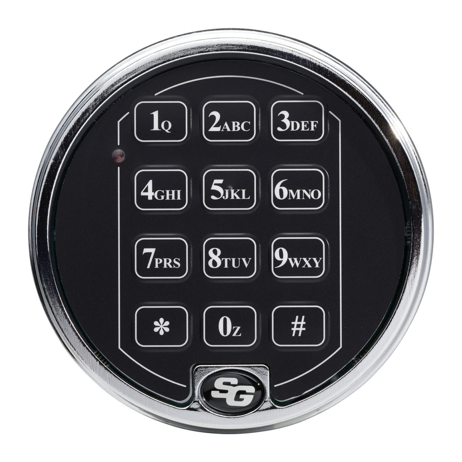
• The keypad diameter is 4 inches (101.6mm). This is slightly greater
than the diameter of standard S&G dial rings for mechanical locks.
The 61KP series keypad will cover any scratches or paint blemishes
left by the old lock.
• Modifications to the lock (including
lock bolt attachments) are not rec-
ommended, and will void the manu-
facturer's warranty.
• A minimum distance of .150"
(3.8mm) is required between the end
of the lock case containing the bolt
and the safe's blocking bar or cam plate which is normally blocked by the extended lock bolt. This is
because the lock bolt may not be retracted quite as far by older batteries as by fresh ones.
• You should install fresh alkaline batteries in the keypad and connect the lock wiring cable to
check the functions of the lock prior to installation. Follow the procedures given in the Operating
Instructions. Avoid pressure to the end of the lock bolt during these checks.
• Do not allow the safe's blocking bar or cam plate to depress the electronic lock's bolt farther
than it retracts during normal motor operation. This can lead to inconsistent lock operation.
• If you are installing a 6126 and will be adding the audit trail/alarm interface, you should also read
those instructions (document 630-523) before beginning the lock and keypad installation.
Sargent & Greenleaf, Inc.
One Security Drive, Nicholasville, Kentucky 40356
Phone (859) 885-9411
FAX (859) 887-2057
Copyright 1998, Sargent & Greenleaf, Inc.
Installation
Instructions
Sargent & Greenleaf S.A.
9, chemin du Croset, 1024 Ecublens, Switzerland
Phone 41-21-691-9583
This document is part number 630-428
FAX 41-21-691-5349
revised 7/9/03
Advertisement

Related Manuals for Sargent and Greenleaf 6124


Summary of Contents for Sargent and Greenleaf 6124
- Page 1 6124/6126 Installation Motorized Electronic Instructions Combination Lock This Sargent & Greenleaf 6100 series electronic lock combines ease of operation with security. Advanced electronic circuit design makes it easy to install, easy to open, and easy to change codes. Follow these instructions carefully to get the best possible performance from your lock.
- Page 2 . . . NSTALLATION OTES Although the model 6100 series is easy to install, we recommend the following procedures be performed only by an experienced locksmith or safe technician. Your safe may incorporate relock- ing devices that are attached to the combination lock. Misalignment or detachment of these devices can result in a lockout—a condition where the safe cannot be opened without damage.
- Page 3 Step 3 Once you’ve made sure the wire cable is not crimped or in contact with any sharp surface, attach the lock to the safe’s mounting plate. Use the three ⁄ -20 (or metric M6) screws provided. Tighten securely so the lock is attached firmly to the plate.
- Page 4 Step 6 The boltwork bind has been relieved by removing a small amount of material from the right side of the boltwork opening. When the safe’s boltwork is fully thrown to the locked position, there is an air space on all sides of the electronic lock’s bolt.
- Page 5 Step 9 The wire cable connector is shaped so that it will fit into the circuit board recep- tacle only when aligned correctly. Insert the connector into its receptacle in the keypad housing. If it does not slide easily into place, do not force it. This means you need to turn it 180º...
- Page 6 Step 11 Place the keypad over the base. Make sure the wire cable is still clear of the three spring clips, then push the keypad firmly onto the base. It should snap into place. Note: To remove the keypad, pull the bottom (area nearest the S&G logo) away from the mounting base first.