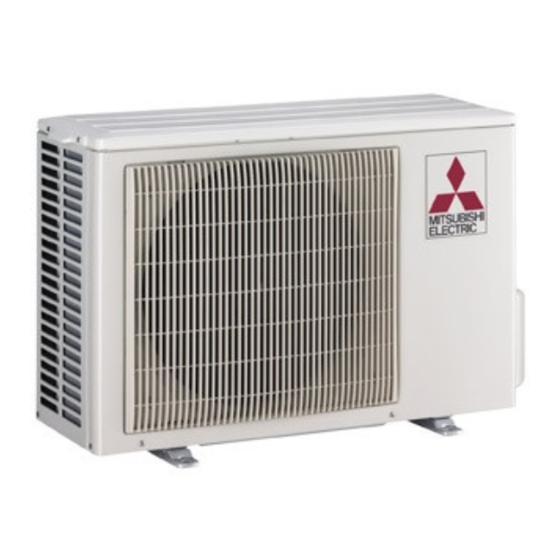
Mitsubishi MUZ-A09NA Service Manual

Mitsubishi MUZ-A09NA Service Manual

Split-type, heat pump air conditioners

Advertisement

SPLIT-TYPE, HEAT PUMP AIR CONDITIONERS

OUTDOOR UNIT

SERVICE MANUAL

MUZ-A12NA
MUZ-A17NA
MUY-A15NA
MUZ-A09NA MUY-A15NA
NOTE:
This service manual describes technical data of the outdoor units.
RoHS compliant products have <G> mark on the spec name plate.
For servicing of RoHS compliant products, refer to the PARTS
LIST (RoHS compliant).
HFC
utilized
R410A
MUZ-A09NA-
MUZ-A12NA-
MUZ-A15NA-
MUZ-A17NA-
MUZ-A24NA-
CONTENTS
1. TECHNICAL CHANGES ····································2
2. PART NAMES AND FUNCTIONS······················5
3. SPECIFICATION·················································6
4. OUTLINES AND DIMENSIONS ·······················10
5. WIRING DIAGRAM···········································11
6. REFRIGERANT SYSTEM DIAGRAM ··············15
7. DATA·································································17
8. ACTUATOR CONTROL····································30
9. SERVICE FUNCTIONS ····································31
10. TROUBLESHOOTING······································31
11. DISASSEMBLY INSTRUCTIONS·····················59
12. PARTS LIST······················································66
12-1. PARTS LIST·············································66
12-2. RoHS PARTS LIST ··································72
13. OPTIONAL PARTS ·························BACK PAGE
No. OB451
U1
U1
U1
U1
U1
Indoor unit service manual
MSZ-A•NA Series (OB450)
TM

Advertisement

Table of Contents
loading

Summary of Contents for Mitsubishi MUZ-A09NA

  • Page 1: Table Of Contents

    6. REFRIGERANT SYSTEM DIAGRAM ··············15 7. DATA·································································17 8. ACTUATOR CONTROL····································30 9. SERVICE FUNCTIONS ····································31 10. TROUBLESHOOTING······································31 11. DISASSEMBLY INSTRUCTIONS·····················59 MUZ-A09NA MUY-A15NA 12. PARTS LIST······················································66 MUZ-A12NA MUY-A17NA 12-1. PARTS LIST·············································66 MUZ-A15NA 12-2. RoHS PARTS LIST ··································72 13. OPTIONAL PARTS ·························BACK PAGE NOTE: This service manual describes technical data of the outdoor units.
  • Page 2: Technical Changes

    TECHNICAL CHANGES MUZ09UN MUZ-A09NA MUZ12UN MUZ-A12NA MUH15TN MUZ-A15NA MUH17TN MUZ-A17NA MUH24WN MUZ-A24NA MU15TN MUY-A15NA MU17TN MUY-A17NA MU24WN MUY-A24NA 1. Outdoor unit model has been changed. 2. Control method between indoor and outdoor unit has been changed. 3. Refrigerant has been changed. (R22 R410A) 4.
  • Page 3 New Specification Current Specification The incompatible refrigeration oil easily separates from Since refrigerant and refrigeration oil are compatible each, refrigerant and is in the upper layer inside the suction muffler. refrigeration oil goes back to the compressor through the Raising position of the oil back hole enables to back the lower position oil back hole.
  • Page 4 2.Refrigerant piping 1 Specifications Use the copper or copper-alloy seamless pipes for refrigerant that meet the following specifications. Outside diameter(in) Wall thickness (in) Insulation material 0.0315 0.0315 Heat resisting foam plastic 0.0315 Specific gravity 0.045 Thickness 0.315 in 0.0394 2 Flaring work and flare nut Flaring work for R410A pipe differs from that for R22 pipe.
  • Page 5: Part Names And Functions

    PART NAMES AND FUNCTIONS MUZ-A09NA MUZ-A15NA MUY-A15NA MUZ-A24NA MUY-A24NA MUZ-A12NA MUZ-A17NA MUY-A17NA Air inlet Air inlet (back and side) (back and side) Piping Piping Drain hose Drain hose Air outlet Air outlet Drain outlet Drain outlet...
  • Page 6: Wireless Type

    10.3 [17.0] HSPF IV(V) Heating 8.2 (6.7) 8.2 (6.7) Heating 3.71 3.44 OUTDOOR UNIT MODEL MUZ-A09NA MUZ-A12NA External finish Munsell 3Y 7.8/1.1 Power supply 208/230, 1, 60 V, phase, Hz Max. fuse size (time delay) Min. circuit ampacity Fan motor F.L.A...
  • Page 7 Model MSZ-A15NA MSY-A15NA MSZ-A17NA MSY-A17NA Item Capacity Cooling Btu/h 15,000 (3,100~15,000) 15,000 (3,100~15,000) 16,200 (3,100~16,200) 16,200 (3,100~16,200) Rated(Minimum~Maximum) Heating 47 Btu/h 18,000 (3,400~20,900) – 20,100 (3,400~20,900) – Capacity Rated Heating 17 Btu/h 13,000 – 13,000 – Cooling Power consumption 1,690 (210~1,690) 1,690 (210~1,690) 2,070 (210~2,070) 2,070 (210~2,070)
  • Page 8 Model MSY-A24NA MSZ-A24NA Item Capacity Cooling 22,000 (4,400~22,000) 22,000 (4,400~22,000) Btu/h Heating 47 Rated(Minimum~Maximum) 23,200 (3,600~24,400) — Btu/h Capacity Rated Heating 17 Btu/h 15,200 — Power consumption Cooling 2,880 (290~2,880) 2,880 (290~2,880) Rated(Minimum~Maximum) Heating 47 2,350 (260~2,570) — Power consumption Rated Heating 17 1,960 —...
  • Page 9 Test condition (Unit : [˚F]) Indoor air condition Outdoor air condition Mode Test Wet bulb Wet bulb Dry bulb Dry bulb SEER "A" Cooling Steady State (75) (Cooling) at rated compressor Speed "B-2" Cooling Steady State (65) at rated compressor Speed "B-1"...
  • Page 10: Muz-A15Na

    OUTLINES AND DIMENSIONS MUZ-A09NA MUZ-A12NA MUZ-A15NA Unit: inch MUZ-A17NA MUY-A15NA MUY-A17NA REQUIRED SPACE Basically open 4inch or more without any obstruction in front 15-3/4 Drainage hole [ 1-5/8 and on both sides of the unit. Air in Air in 1-9/16...
  • Page 11: Wiring Diagram

    WIRING DIAGRAM MUZ-A09NA MUZ-A12NA MUZ-A15NA MUZ-A17NA...
  • Page 12 MUY-A15NA MUY-A17NA...
  • Page 13 MUZ-A24NA...
  • Page 14 MUY-A24NA...
  • Page 15: Refrigerant System Diagram

    REFRIGERANT SYSTEM DIAGRAM MUZ-A09NA MUZ-A15NA MUY-A15NA Unit:inch MUZ-A12NA MUZ-A17NA MUY-A17NA Refrigerant pipe [3/8 (MUZ-A09/12) [1/2 (MUZ-A15/17,MUY-A15/17) (with heat insulator) 4-way valve Muffler Stop valve (with service port) Outdoor Muffler Discharge heat Flared connection exchanger temperature Service thermistor port RT62 Ambient...
  • Page 16 (with heat insulator) ([3.6 o [2.4 o 50) MAX. REFRIGERANT PIPING LENGTH and MAX. HEIGHT DIFFERENCE Refrigerant piping : ft Piping size O.D : in Max. length Max. Height difference Model Liquid MUZ-A09NA MUZ-A12NA MUZ-A15NA MUY-A15NA MUZ-A17NA MUY-A17NA MUZ-A24NA MUY-A24NA Indoor unit Max.
  • Page 17: Data

    MUY-A24NA Calculation : Xoz. = 1.08/ 5oz./ ft o (Refrigerant piping length (ft)-25) NOTE : Refrigerant piping exceeding 25ft. requies additional refrigerant charge according to the calculation. DATA MUZ-A09NA MUZ-A12NA MUZ-A15NA MUZ-A17NA MUZ-A24NA MUY-A15NA MUY-A17NA MUY-A24NA 7-1. PERFORMANCE DATA 1) COOLING CAPACITY Outdoor intake air DB temperature ( ˚F )
  • Page 18 3) HEATING CAPACITY Outdoor intake air WB temperature ( ˚F ) Indoor air Model ( ˚F ) 0.64 0.75 0.84 10.6 0.88 11.0 0.89 12.4 0.93 MSZ-A09NA 0.62 0.74 0.82 10.9 0.86 11.2 0.88 12.7 0.91 0.59 0.71 10.0 0.80 11.2 0.84 11.6...
  • Page 19: Performance Curve

    7-2. PERFORMANCE CURVE Cooling MSZ-A09NA MSZ-A12NA MSZ-A15NA MSY-A15NA SHF at rating condition = 0.70 SHF at rating condition = 0.65 SHF at rating condition = 0.71 = 318CFM Airflow Airflow = 342CFM Airflow = 275CFM Outdoor intake air DB temperature (°F) Outdoor intake air DB temperature (°F) Outdoor intake air DB temperature (°F) MSZ-A24NA MSY-A24NA...
  • Page 20 7-3. Condensing pressure Cooling Data is based on the condition of indoor humidity 50%. Air flow should be set to High speed. MSZ-A09NA (PSIG) (PSIG) 68 70 105(°F) 68 70 105(°F) Outdoor ambient temperature Outdoor ambient temperature MSZ-A12NA (PSIG) (PSIG) 68 70 105(°F) 68 70...
  • Page 21 MSZ-A17NA MSY-A17NA (PSIG) (PSIG) 68 70 105(°F) 68 70 105(°F) Outdoor ambient temperature Outdoor ambient temperature MSZ-A24NA MSY-A24NA (PSIG) (PSIG) 68 70 105(°F) 68 70 105(°F) Outdoor ambient temperature Outdoor ambient temperature...
  • Page 22 Heating Data is based on the condition of outdoor humidity 75%. Air flow should be set to High speed. Data is for heating operation without any frost. MSZ-A09NA (PSIG) (PSIG) 58Hz 58Hz 20 25 30 35 40 45 50 55 60 65 70 65 70(°F) (°F) Outdoor ambient temperature...
  • Page 23 MSZ-A17NA (PSIG) (PSIG) 58Hz 58Hz 20 25 30 35 40 45 50 55 60 65 70 (°F) 65 70(°F) Outdoor ambient temperature Outdoor ambient temperature MSZ-A24NA (PSIG) (PSIG) 58Hz 58Hz 20 25 30 35 40 45 50 55 60 65 70 65 70(°F) (°F) Outdoor ambient temperature...
  • Page 24 0.016 0.021 Fan motor current 0.18 / 0.16 0.23 / 0.21 Aux. heater current – – Electrical circuit Outdoor unit MUZ-A09NA MUZ-A12NA Power supply (V, phase, Hz) 208/230, 1, 60 208/230, 1, 60 Input 0.674 0.844 1.149 1.139 Comp. current 2.80 / 2.53...
  • Page 25 MSZ-A17NA MSZ-A15NA Model MSZ-A15NA MSZ-A17NA MSY-A17NA MSY-A15NA Item Unit Cooling Cooling Heating Heating Capacity Btu / h 15,000 18,000 16,200 20,100 — 0.65 – 0.65 – Total Input 1.69 1.79 2.07 2.15 Rated frequency MSZ-A15NA, MSY-A15NA MSZ-A17NA, MSY-A17NA Indoor unit 208/230, 1, 60 208/230, 1, 60 Power supply (V, phase, Hz)
  • Page 26 MSZ-A24NA MSZ-A24NA Model MSY-A24NA Item Unit Cooling Heating Capacity Btu / h 22,000 23,200 — 0.63 – Total Input 2.88 2.35 Rated frequency Indoor unit MSZ-A24NA , MSY-A24NA Power supply (V, phase, Hz) 208/230, 1, 60 Input 0.053 0.52 / 0.47 Fan motor current Aux.
  • Page 27 7-5. OPERATING RANGE (1) POWER SUPPLY Rated voltage Guaranteed Voltage Min. 198V 208V 230V Max. 253V Outdoor unit 208/230V 1phase 60Hz (2) OPERATION Intake air Indoor Outdoor temperature Function DB (˚F) WB (˚F) DB (˚F) WB (˚F) Condition Standard temperature —...
  • Page 28 7-6. Capacity and input correction by inverter output frequency MUZ-A09NA Correction of Heating total input Correction of Cooling capacity Correction of Cooling total input Correction of Heating capacity 150(Hz) 150(Hz) 150(Hz) 150(Hz) The operational frequency of compressor The operational frequency of compressor...
  • Page 29: Muz-A24Na

    MUZ-A17NA MUY-A17NA MUZ-A17NA Correction of Cooling capacity Correction of Cooling total input Correction of Heating total input Correction of Heating capacity (Hz) (Hz) (Hz) (Hz) The operational frequency of compressor The operational frequency of compressor The operational frequency of compressor The operational frequency of compressor MUZ-A24NA MUY-A24NA...
  • Page 30: Actuator Control

    ACTUATOR CONTROL MUZ-A09NA MUZ-A12NA MUZ-A15NA MUZ-A17NA MUZ-A24NA MUY-A15NA MUY-A17NA MUY-A24NA 8-1. Outdoor fan motor control The fan motor turns ON/OFF, interlocking with the compressor. [ON] The fan motor turns ON 5 seconds before the compressor starts up. [OFF] The fan motor turns OFF 15 seconds after the compressor has stopped running.
  • Page 31: Service Functions

    (Initial setting) none 55°F (13°C) 46°F (8°C) (cut) TROUBLESHOOTING MUZ-A09NA MUZ-A12NA MUZ-A15NA MUZ-A17NA MUZ-A24NA MUY-A15NA MUY-A17NA MUY-A24NA 10-1. Cautions on troubleshooting 1. Before troubleshooting, check the following: 1) Check the power supply voltage. 2) Check the indoor/outdoor connecting wire for mis-wiring.
  • Page 32: Failure Mode Recall Function

    10-2. Failure mode recall function Outline of the function This air conditioner can memorize the abnormal condition which has occurred once. Even though LED indication listed on the troubleshooting check table (10-3.) disappears, the memorized failure details can be recalled. This mode is very useful when the unit needs to be repaired for the abnormality which doesn't recur.
  • Page 33 2. Flow chart of the detailed outdoor unit failure mode recall function Operational procedure The outdoor unit might be abnormal. Confirm if outdoor unit is abnormal according to the following procedures. Confirm that the remote controller is in the failure mode recall function.
  • Page 34 3. Outdoor unit failure mode table MUZ-A09/12/15/17NA MUY-A15/17NA The left lamp of Indoor/outdoor Outdoor unit Abnormal point LED indication Correspondence Condition OPERATION INDICATOR unit failure mode failure mode (Failure mode / protection) (Outdoor P.C. board) recall function recall function lamp(Indoor unit) None (Normal) Outdoor power system When it consecutively occurs 3 times...
  • Page 35 MUZ-A24NA MUY-A24NA The left lamp of LED indication Indoor/outdoor Abnormal point OPERATION INDICATOR (Outdoor P.C. board) Condition Correspondence unit failure mode (Failure mode / protection) recall function lamp(Indoor unit) LED 1 LED 2 Non (Normal) 2-time flash Outdoor power system Lighting Lighting When IPM protection stop or lock •...
  • Page 36 LED indication The left lamp of Indoor/outdoor Abnormal point Condition Correspondence (Outdoor P.C. board) OPERATION INDICATOR unit failure mode (Failure mode / protection) recall function lamp(Indoor unit) LED 1 LED 2 Communication error 11-time flash Communication error occurs Lighting 6 times •...
  • Page 37: Troubleshooting Check Table

    10-3. Troubleshooting check table MUZ-A09/12/15/17NA MUY-A15/17NA Symptom LED indication Abnormal point/ Condition Condition Correspondence · Check stop valve. When it consecutively occurs 3 times that the compressor stops 1-time flash every Outdoor power Outdoor unit · Reconnect connector of compressor. for overcurrent protection within 1minute after start-up.
  • Page 38 MUZ-A24NA MUY-A24NA Indication Symptom Abnormal point / Condition Condition Correspondence LED1(Red) LED2(Yellow) Outdoor unit • Check the connection of the compressor connecting When IPM protection stop or lock protection stop is continuously does not wire. performed three times within 1 minute after the compressor gets operate.
  • Page 39 Indication No. Symptom Abnormal point / Condition Condition Correspondence LED1(Red) LED2(Yellow) Outdoor unit Primary current protection When the input current exceeds 15A. Once Lighting operates. Secondary current protection When the current of the compressor exceeds 15A. These symptoms do not mean any abnormality of the product, but check the following points.
  • Page 40 10-4. Trouble criterion of main parts MUZ-A09NA MUZ-A12NA MUZ-A15NA MUZ-A17NA MUY-A15NA MUY-A17NA Part name Check method and criterion Figure Defrost thermistor Measure the resistance with a tester. (RT61) (MUZ) Refer to 10-6. "Test point diagram and voltage", 1. "Inverter P.C. board", Ambient temperature the chart of thermistor.
  • Page 41 MUZ-A24NA MUY-A24NA Part name Check method and criterion Figure Defrost thermistor Measure the resistance with a tester. (RT61) (MUZ) Ambient temperature Refer to 10-6. “Test point diagram and voltage”,3. “Outdoor electronic thermistor (RT65) control P.C. board”, the chart of thermistor. Outdoor heat exchanger temperature thermistor (RT68)
  • Page 42 10-5. Troubleshooting flow When OPERATION / INDICATOR lamp flashes 5-time. Outdoor unit does not operate. How to check inverter/ compressor MUZ-A09/12/15/17 MUY-A15/17 Disconnect the connector (CN61) between compressor and the intelligent power module (IPM). Check the voltage See 10-5.B “Check of open phase” . between terminals.
  • Page 43 Check of open phase MUZ-A09/12/15/17 MUY-A15/17 With the connector between the compressor and the intelligent power module disconnected, activate the inverter and check if the inverter is normal by measuring the balance of voltage between the terminals. Output voltage 115V <<...
  • Page 44 Check of compressor operation time MUZ-A09/12/15/17 MUY-A15/17 Outdoor fan starts 0 second Connect the compressor and activate the inverter. Then measure the Abnormal time until the inverter stops due to over current. (Compressor winding short or layer short) <<Operation method>> (Compressor connector poor contact) Start heating or cooling operation by pressing EMERGENCY (Compressor lock-out)
  • Page 45 • When OPERATION INDICATOR lamp flashes 6-time. • When thermistor is abnormal. G G Check of outdoor thermistors MUZ-A24 MUY-A24 Disconnect the connector in the outdoor electronic control P.C. board or the outdoor power board Replace the thermistor. (see below table), and measure the resistance of thermistor. Is the thermistor normal? (Refer to 10-6.3.) Reconnect the connector CN661 on the outdoor electronic control P.C.
  • Page 46 The cooling operation or heating operation does not operate. (LED display: Both LED1 and LED2 lighting) H H Check of R.V. coil MUZ-A24 • When heating operation does not work. 1. Disconnect the lead wire leading to the compressor. 2. 3 minutes after turning on the power supply, start EMERGENCY OPERATION in HEAT mode.
  • Page 47 Outdoor fan motor does not operate. Check of outdoor fan motor MUZ-A09/12/15/17 MUY-A15/17 Rotate the outdoor fan slowly by hand, and measure the Is the resistance Disconnect CN932 voltage of CN931 (Measurement between each terminal of Turn ON the from the inverter of feedback output).
  • Page 48 Inverter does not operate. Check of power supply MUZ-A09/12/15/17 MUY-A15/17 Disconnect the connector (CN61) between compressor and intelligent power module. Turn ON power supply and press Rectify indoor/ outdoor EMERGENCY OPERATION connecting wire. switch. Does the left lamp of Is there voltage 230V AC OPERATION INDICATOR Replace the indoor between the indoor...
  • Page 49 Outdoor unit does not operate at all, or stops immediately due to overcurrent. Check of current-limiting resistor MUZ-A09/12/15/17 MUY-A15/17 When the current-limiting resistor is open, the rush current limiting relay (X64) may not work properly. Is the resistance of current-limiting Turn ON the power Replace the power P.C.
  • Page 50: Check Of Lev (Expansion Valve)

    Heating/Cooling does not work sufficiently. Check of LEV (Expansion valve) MUZ-A09/12/15/17 MUY-A15/17 Turn ON the power supply. This figures show about MSZ-A09/12/15/17. < Preparation of the remote controller > 1 While pressing both OPERATION SELECT button and TOO COOL button on the remote controller at the same time, press RESET button.
  • Page 51 • When cooling, heat exchanger of non-operating indoor unit frosts. • When heating, non-operating indoor unit get warm. Check of LEV LED display: LED1 LED2 Lighting Lighting MUZ-A24 MUY-A24 6 time Goes out Turn on power supply to the outdoor unit after checking LEV coil is mounted to the LEV body securely.
  • Page 52 • When unit cannot operate neither by the remote controller nor by EMERGENCY OPERATION switch. Indoor unit does not operate. • When OPERATION INDICATOR lamp flashes ON and OFF in every 0.5-second. Outdoor unit doesn’t operate. How to check mis-wiring and serial signal error (when outdoor unit does not work) Turn OFF the power supply.
  • Page 53: Electromagnetic Noise Enters Into Tv Sets Or Radios

    Electromagnetic noise enters into TV sets or radios Is the unit earthed? Earth the unit. Is the distance between the Extend the distance between antennas and the indoor the antennas and the indoor unit within 9.91ft., or is the unit, and/or the antennas and distance between the the outdoor unit.
  • Page 54 10-6. Test point diagram and voltage 1. Inverter P.C. board MUZ-A09NA MUZ-A12NA MUZ-A15NA MUZ-A17NA MUY-A15NA MUY-A17NA Back side of unit 208/230V AC Smoothing capacitor Smoothing capacitor Smoothing capacitor DB61 DB61 (C63C) (C63B) (C63A) 280V ~ 370V LED monitor lamp Output to...
  • Page 55 2. Power P.C. board MUZ-A09NA MUZ-A12NA MUZ-A15NA MUZ-A17NA MUY-A15NA MUY-A17NA Back side of unit Front side of unit Varistor Varistor Varistor (NR63) (NR62) (NR64) 208/230V AC R.V.coil (CN721) 208/230V AC Connecting wire with inverter P.C.board (CN726)
  • Page 56 3. Outdoor electronic control P.C. board MUZ-A24NA MUY-A24NA Defrost thermistor (RT61) Ambient temperature thermistor (RT65) Outdoor heat exchanger temperature thermistor (RT68) Fin temperature thermistor (RT64) Discharge temperature thermistor (RT62) 32 50 68 84 104 122 140 158 176 104 122 140 176 194 122 212 230 248 Temperature (°F) Temperature (°F) Temperature (°F)
  • Page 57 4. Noise filter P.C. board MUZ-A24NA MUY-A24NA CN901 To electronic CN902 CN903 control To power To power P.C. board board board 208/230V AC 60Hz Input CN912 R.V. coil 208/230V AC 60Hz Output 208/230V AC 208/230V AC 60Hz 60Hz Output Output F64 FUSE F911 FUSE NR64 VARISTOR...
  • Page 58 5. Outdoor power board MUZ-A24NA MUY-A24NA Connect to the compressor Voltage among phases: 5V to 180V 294-370V DC Output (Red) (–) (White) Connect to the earth Signal reception (From electronic control P.C. board) 5V DC pulse wave Fin temperature thermistor RT64 Primary current detection (Connect to the noise filter) Connect to the controller board...
  • Page 59: Disassembly Instructions

    2Pull the terminal while pull out the terminal pushing the locking slowly. Locking lever lever. Connector 11-1. MUZ-A09NA MUZ-A12NA MUZ-A15NA MUZ-A17NA MUY-A15NA MUY-A17NA PHOTOS OPERATING PROCEDURE Photo 1 1. Removing the cabinet. (1) Remove the screw fixing the service panel. (See Photo 1.) (2) Pull down the service panel and remove it.
  • Page 60 OPERATING PROCEDURE PHOTOS 2. Removing the inverter assembly, inverter P.C. board Photo 3 Screws of the and power P.C. board relay panel (1) Remove the top panel, cabinet and service panel. (Refer to 1.) Screws of (2) Disconnect the power supply and indoor/outdoor the ground wires connecting wire and remove the back panel.
  • Page 61 OPERATING PROCEDURE PHOTOS Photo 6 5. Removing outdoor fan motor (1) Remove the top panel, cabinet and service panel. (Refer to 1.) (2) Disconnect the power supply and indoor/outdoor connecting wire and remove the back panel. (Refer to 1.) (3) Disconnect the connectors for outdoor fan motor. (4) Remove the propeller nut.
  • Page 62 11-2. MUZ-A24NA MUY-A24NA OPERATING PROCEDURE PHOTOS 1. Removing the cabinet Photo 1 Screw of the top panel (1) Remove the screws of the service panel. (2) Remove the screws of the top panel. (3) Remove the screw of the valve cover. (4) Remove the service panel.
  • Page 63 OPERATING PROCEDURE PHOTOS 2. Removing the inverter assembly, inverter P.C. board Photo 4 and power board Screws of the power board assembly (1) Remove the top panel, cabinet and service panel. (Refer to 1.) (2) Remove the back panel.(Refer to 1.) (3) Disconnect the following connectors;...
  • Page 64 OPERATING PROCEDURE PHOTOS 4. Removing the defrost thermistor (MUZ), discharge Photo 5 Discharge temperature thermistor temperature thermistor, outdoor heat exchanger temperature thermistor and ambient temperature thermistor (1) Remove the top panel, cabinet and service panel. (Refer to 1.) (2) Remove the back panel. (Refer to 1.) (3) Remove the inverter assembly.
  • Page 65 OPERATING PROCEDURE PHOTOS 6. Removing the compressor and 4-way valve Photo 8 (1) Remove the top panel, cabinet and service panel. (Refer to 1.) (2) Remove the back panel. (Refer to 1.) (3) Remove the inverter assembly. (Refer to 2.) (4) Recover gas from the refrigerant circuit.
  • Page 66: Parts List

    PARTS LIST 12-1. PARTS LIST (non-RoHS compliant) MUZ-A09NA MUZ-A12NA MUZ-A15NA MUZ-A17NA MUY-A15NA MUY-A17NA 1. OUTDOOR UNIT STRUCTURAL PARTS AND FUNCTIONAL PARTS...
  • Page 67 MUZ-A09NA MUZ-A12NA MUZ-A15NA MUZ-A17NA MUY-A15NA MUY-A17NA 1. OUTDOOR UNIT STRUCTURAL PARTS AND FUNCTIONAL PARTS Part numbers that are circled are not shown in the illustration. Symbol Q'ty/unit MUZ- MUY- in Wiring Part Name Remarks Part No. Diagram A09NA A12NA A15NA A17NA A15NA A17NA...
  • Page 68 MUZ-A09NA MUZ-A12NA MUZ-A15NA MUZ-A17NA MUY-A15NA MUY-A17NA 2. OUTDOOR UNIT ELECTRICAL PARTS...
  • Page 69 MUZ-A09NA MUZ-A12NA MUZ-A15NA MUZ-A17NA MUY-A15NA MUY-A17NA 2. OUTDOOR UNIT ELECTRICAL PARTS Part numbers that are circled are not shown in the illustration. Q'ty/unit Symbol in Wiring Part No. Part Name MUZ- MUY- Remarks Diagram A09NA A12NA A15NA A17NA A15NA A17NA...
  • Page 70 MUZ-A24NA MUY-A24NA 3. OUTDOOR UNIT STRUCTURAL PARTS, ELECTRICAL PARTS AND FUNCTIONAL PARTS...
  • Page 71 MUY-A24NA MUY-A24NA 3. OUTDOOR UNIT STRUCTURAL PARTS, ELECTRICAL PARTS AND FUNCTIONAL PARTS Part numbers that are circled are not shown in the illustration. Q'ty/unit Symbol Part No. Part Name Remarks in Wiring MUZ-A24NA MUY-A24NA Diagram E02 819 297 TOP PANEL E02 A53 630 OUTDOOR HEAT EXCHANGER E02 A58 630...
  • Page 72: Rohs Parts List

    12-2. RoHS PARTS LIST (RoHS compliant) MUZ-A09NA MUZ-A12NA MUZ-A15NA MUZ-A17NA MUY-A15NA MUY-A17NA 1. OUTDOOR UNIT STRUCTURAL PARTS AND FUNCTIONAL PARTS...
  • Page 73 MUZ-A09NA MUZ-A12NA MUZ-A15NA MUZ-A17NA MUY-A15NA MUY-A17NA 1. OUTDOOR UNIT STRUCTURAL PARTS AND FUNCTIONAL PARTS Part numbers that are circled are not shown in the illustration. Q'ty/unit Symbol MUZ-A MUY-A in Wiring Part No. Part Name Remarks 09NA 12NA 15NA 17NA 15NA17NA...
  • Page 74 MUZ-A09NA MUZ-A12NA MUZ-A15NA MUZ-A17NA MUY-A15NA MUY-A17NA 2. OUTDOOR UNIT ELECTRICAL PARTS...
  • Page 75 MUZ-A09NA MUZ-A12NA MUZ-A15NA MUZ-A17NA MUY-A15NA MUY-A17NA 2. OUTDOOR UNIT ELECTRICAL PARTS Part numbers that are circled are not shown in the illustration. Q'ty/unit Symbol MUZ-A MUY-A Part No. Part Name in Wiring Remarks 09NA 12NA 15NA 17NA 15NA 17NA Diagram...
  • Page 76 MUZ-A24NA MUY-A24NA 3. OUTDOOR UNIT STRUCTURAL PARTS, ELECTRICAL PARTS AND FUNCTIONAL PARTS...
  • Page 77 MUY-A24NA MUY-A24NA 3. OUTDOOR UNIT STRUCTURAL PARTS, ELECTRICAL PARTS AND FUNCTIONAL PARTS Part numbers that are circled are not shown in the illustration. Q'ty/unit Symbol Part No. Part Name Remarks in Wiring MUZ-A24NA MUY-A24NA Diagram E12 819 297 TOP PANEL E12 A53 630 OUTDOOR HEAT EXCHANGER E12 A58 630...
  • Page 78: Optional Parts

    Parts No. MUZ-A09/12/15/17NA MAC-851DS MUY-A15/17NA 13-2. DRAIN SOCKET ASSEMBLY Model Parts No. MUZ-A24NA MAC-811DS MUY-A24NA C C Copyright 2006 MITSUBISHI ELECTRIC ENGINEERING CO.,LTD New publication, effective Apr. 2006 Distributed in Apr. 2006. No. OB451 7 Specifications subject to change without notice.
  • Page 79 3400 Lawrenceville Suwanee Road Suwanee, Georgia 30024 ● Toll Free: 800-433-4822 Toll Free Fax: 800-889-9904 ● www.mrslim.com Specifications are subject to change without notice.

Table of Contents