Table of Contents
Advertisement
SPLIT-TYPE AIR CONDITIONERS
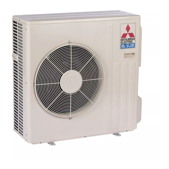
OUTDOOR UNIT
SERVICE MANUAL
Models
MUZ-D30NA / -
MUZ-D36NA / -
MUY-D30NA / -
MUY-D36NA / -
NOTE:
RoHS compliant products have <G> mark on the spec name plate.
HFC
utilized
R410A
/ -
/ -
1
U1
U2
/ -
/ -
1
U1
U2
1
1
CONTENTS
1. TECHNICAL CHANGES ··································· 3
2. PART NAMES AND FUNCTIONS ····················· 3
3. SPECIFICATION ················································ 4
4. OUTLINES AND DIMENSIONS ························ 6
5. WIRING DIAGRAM ············································ 7
6. REFRIGERANT SYSTEM DIAGRAM ··············11
7. DATA ································································ 13
8. ACTUATOR CONTROL ··································· 20
9. SERVICE FUNCTIONS ··································· 21
10. TROUBLESHOOTING ····································· 22
11. DISASSEMBLY INSTRUCTIONS ···················· 41
PARTS CATALOG (OBB502)
• Errors in TROUBLESHOOTING have been
corrected.
Please void OBH502 REVISED EDITION-B.
No. OBH502
REVISED EDITION-C
Indoor unit service manual
MSZ-D•NA Series (OBH501)
MSY-D•NA Series (OBH501)
TM
Advertisement
Table of Contents
Troubleshooting

Summarization of Contents
1 TECHNICAL CHANGES
New Model Introduction
Details about the introduction of new models in the series.
Component Updates
Information on changes to the wiring diagram and fan motor.
2 PART NAMES AND FUNCTIONS
Outdoor Unit Components Overview
Diagram illustrating the components and airflow paths of the outdoor unit.
OPERATING RANGE
Power Supply Specifications
Details on the required power supply voltage and frequency.
Operational Conditions
Defines the operating conditions for cooling and heating modes.
7 DATA
Performance Data
Includes cooling capacity, corrections, and heating capacity tables.
8 ACTUATOR CONTROL
Fan Motor and RV Coil Control
Control logic for the outdoor fan motor and the reversing valve (RV) coil.
Sensor-Actuator Relation
Table showing the relationship between sensors and actuators.
9 SERVICE FUNCTIONS
Pre-Heat and Defrost Settings
Procedures for activating pre-heat control and changing defrost settings.
10 TROUBLESHOOTING
Cautions and Procedures
General safety precautions and basic troubleshooting steps.
10-2. FAILURE MODE RECALL FUNCTION
Function Outline and Flowchart
Explains the failure recall function and provides a flowchart for indoor/outdoor units.
10-5. TROUBLESHOOTING FLOW
Inverter/Compressor Check
Flowchart for checking the inverter and compressor.
Outdoor Thermistors Check
Procedure for checking the resistance of outdoor thermistors.
R.V. Coil Check
Troubleshooting steps for the reversing valve (R.V.) coil.
Outdoor Fan Motor & Power Supply Checks
Checks for the outdoor fan motor and power supply circuit.
Compressor Start Failure & LEV Checks
Diagnosing compressor start issues and LEV functionality.
Miswiring and Serial Signal Error Check
Steps to identify and resolve miswiring and serial signal errors.
HPS and Bus-bar Voltage Checks
Troubleshooting for High Pressure Switch (HPS) and bus-bar voltage.
10-6. TEST POINT DIAGRAM AND VOLTAGE
Outdoor Electronic Control P.C. Board
Diagram and test points for the outdoor electronic control board.
Noise Filter P.C. Board
Diagram and test points for the noise filter P.C. board.
Outdoor Power Board
Diagram and test points for the outdoor power board.
11 DISASSEMBLY INSTRUCTIONS
Terminal Detaching Methods
Illustrates how to detach terminals with and without locking mechanisms.
Removing the Cabinet
Step-by-step instructions for removing the outdoor unit cabinet.
Removing Inverter, Boards, and Power Board
Procedure for removing the inverter assembly, electronic control board, and power board.
Removing Thermistors and Fan Motor
Instructions for removing thermistors and the outdoor fan motor.
Removing Compressor, 4-way Valve, and Reactor
Steps for removing the compressor, 4-way valve, and reactor.


Need help?
Do you have a question about the MUZ-D36NA and is the answer not in the manual?
Questions and answers