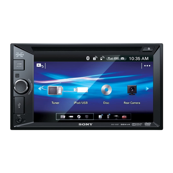
Sony XAV-68BT Service Manual
Av center
Hide thumbs
Also See for XAV-68BT:
- Operating instructions manual (104 pages) ,
- Operating instructions manual (76 pages) ,
- Operating instructions manual (41 pages)
Table of Contents
Advertisement
SERVICE MANUAL
Ver. 1.3 2015.01
(US and Canadian models only)
FOR THE CUSTOMERS IN THE USA. NOT
APPLICABLE IN CANADA, INCLUDING IN THE
PROVINCE OF QUEBEC.
POUR LES CLIENTS AUX ÉTATS-UNIS. NON
APPLICABLE AU CANADA, Y COMPRIS LA
PROVINCE DE QUÉBEC.
AUDIO POWER SPECIFICATIONS
CEA2006 Standard
Power Output: 17 Watts RMS × 4 at
4 Ohms < 1% THD+N
SN Ratio: 80 dBA
(reference: 1 Watt into 4 Ohms)
Monitor section
Display type: Wide LCD color monitor
Dimensions: 6.2 in
System: TFT active matrix
Number of pixels:
1,152,000 pixels (800 × 3 (RGB) × 480)
Color system:
PAL/NTSC/SECAM/PAL-M automatic select
Tuner section (US, Canadian and E (NTSC) models)
FM
Tuning range:
87.5 – 107.9 MHz
FM tuning step: 100 kHz/200 kHz switchable
(E (NTSC) model only)
Antenna (aerial) terminal:
External antenna (aerial) connector
Intermediate frequency: 150 kHz
Usable sensitivity: 10 dBf
Selectivity: 70 dB at 400 kHz
Signal-to-noise ratio: 70 dB (mono)
Separation at 1 kHz: 30 dB
Frequency response: 20 - 15,000 Hz
AM
Tuning range: 530 – 1,710 kHz
Antenna (aerial) terminal:
External antenna (aerial) connector
Intermediate frequency:
9,267.5 kHz or 9,257.5 kHz/5 kHz
Sensitivity: 44 μV
9-896-015-04
Sony Corporation
2015A33-1
©
2015.01
Published by Sony Techno Create Corporation
XAV-68BT
Model Name Using Similar Mechanism
Mechanism Type
SPECIFICATIONS
Tuner section (AEP, Russian, UK, E (PAL),
Saudi Arabia, Indian and Australian models)
FM
Tuning range: 87.5 – 108.0 MHz
Antenna (aerial) terminal:
External antenna (aerial) connector
Intermediate frequency: 150 kHz
Usable sensitivity: 10 dBf
Selectivity: 70 dB at 400 kHz
Signal-to-noise ratio: 70 dB (mono)
Separation at 1 kHz: 30 dB
Frequency response: 20 - 15,000 Hz
AM
Tuning range: 531 – 1,602 kHz
Antenna (aerial) terminal:
External antenna (aerial) connector
Intermediate frequency:
9,267 kHz or 9,258 kHz/4.5 kHz
Sensitivity: 44 μV
DVD/CD Player section
Signal-to-noise ratio: 80 dB
Frequency response: 20 – 20,000 Hz
Wow and flutter: Below measurable limit
Harmonic distortion: 0.05%
Region code: Labeled on the bottom of the unit
USB Player section
Interface: USB (Full-speed)
Maximum current: 1 A
Wireless Communication
Communication System:
BLUETOOTH Standard version 3.0
Output:
BLUETOOTH Standard Power Class 2 (Max. +4
dBm)
Maximum communication range:
Line of sight approx. 10 m (33 ft)*
1
Frequency band:
2.4 GHz band (2.4000 – 2.4835 GHz)
Modulation method: FHSS
Compatible BLUETOOTH Profiles*
2
:
A2DP (Advanced Audio Distribution Profile) 1.2
AVRCP (Audio Video Remote Control Profile) 1.4
HFP (Handsfree Profile) 1.6
PBAP (Phone Book Access Profile)
OPP (Object Push Profile)
SPP (Serial Port Profile)
*1 The actual range will vary depending on factors such
as obstacles between devices, magnetic fields
around a microwave oven, static electricity,
reception sensitivity, antenna's performance,
operating system, software application, etc.
*2 BLUETOOTH standard profiles indicate the purpose
of BLUETOOTH communication between devices.
Canadian Model
Australian Model
Power amplifier section
Outputs: Speaker outputs
Speaker impedance: 4 – 8 ohms
Maximum power output: 55 W × 4 (at 4 ohms)
General
Outputs:
Video output terminal (rear)
Audio output terminals (front, rear/sub
switchable)
Power antenna (aerial)/Power amplifier control
terminal (REM OUT)
Inputs:
Illumination control terminal
Remote controller input terminal
Antenna (aerial) input terminal
Microphone input terminal
Parking brake control terminal
Reverse input terminal
Camera input terminal
AUX audio input terminal (Front)
AUX Audio/Video input terminal (Rear)
USB port
External input terminal (E (PAL), Saudi Arabia,
Indian and Australian models only)
Power requirements: 12 V DC car battery
(negative ground (earth))
Dimensions: Approx. 178 mm × 101.5 mm × 169 mm
(7
1
/
× 4 × 6
3
/
in) (w/h/d)
8
4
Mounting dimensions:
(Except AEP, Russian and UK models)
Approx. 178 mm × 100 mm × 165 mm
(7
1
/
× 4 × 6
1
/
in) (w/h/d)
8
2
(AEP, Russian and UK models)
Approx. 182 mm × 100.6 mm × 159 mm
(7
1
/
× 4
3
/
× 6
3
/
in) (w/h/d)
4
8
8
Mass: Approx. 1.7 kg (3 lb 12 oz)
Package contents:
Parts for installation and connections (1 set)
Remote Commander (1): RM-X170
Microphone (1)
Design and specifications are subject to change
without notice.
Region code
The region system is used to protect software
copyrights.
The region code is located on the bottom of the
unit, and only DVDs labeled with an identical region
code can be played on this unit.
DVDs labeled
can also be played.
If you try to play any other DVD, the message
[Playback prohibited by region code.] will appear
on the monitor screen. Depending on the DVD, no
region code may be labeled even though playing
the DVD is prohibited by area restrictions.
US Model
AEP Model
UK Model
E Model
XAV-65
DR28N-ABB-YG
AV CENTER
Advertisement
Table of Contents

Related Manuals for Sony XAV-68BT


Summary of Contents for Sony XAV-68BT
-
Page 1: Specifications
BLUETOOTH communication between devices. on the monitor screen. Depending on the DVD, no region code may be labeled even though playing the DVD is prohibited by area restrictions. 9-896-015-04 Sony Corporation 2015A33-1 © 2015.01 Published by Sony Techno Create Corporation... -
Page 2: Table Of Contents
The Bluetooth® word mark and logos are registered 3-8. BT Board ................. 19 trademarks owned by Bluetooth SIG, Inc. and any use of such marks by Sony Corporation is under license. Other trademarks and trade names are those of their respective owners. -
Page 3: Servicing Notes
(US, Canadian, AEP, Russian, UK, IMPORTANT NOTE FOR REPAIRING E (PAL) and Saudi Arabia models) XAV-68BT contain individual information that the customer regis- tered because it installs the Bluetooth function. When repairing, the data that the customer registered might disap- Region Code pear. - Page 4 XAV-68BT NOTE FOR TRANSPORTATION NOTE OF REPLACING THE CHASSIS MAIN ASSY (CHA1) When this unit is transported, it is necessary to install two transpor- When the chassis MAIN assy (CHA1) is replaced, the destination tation screws. Please transport it after installing two transportation setting is necessary.
- Page 5 MCU: SONY-ST02-140515 Graphic: SONY-TW02-140514 Mecha: SONY-SP02-140514 Servo: HI6CD1-BBA-893D BT: H10077-V2R78-20001 / SONY:XAV-68BT 3. The resetting operation is executed by pressing the [ENTER] button on the remote commander the confi rming ends, and the unit returns to the normal condition. 4. Processing After the Destination Setting Be sure to unsolder the SL001 on the MAIN board after doing the destination setting.
-
Page 6: General
XAV-68BT SECTION 2 This section is extracted GENERAL from instruction manual. (US and Canadian models) À la borne +12 V qui est alimentée lorsque la Français English To a car’s illumination signal clé de contact est sur la position accessoires Español... - Page 7 Dans le cas contraire, consultez votre Precauciones Mises en garde no pudiera, consulte al distribuidor Sony más cercano. d’installation pour que l’appareil ne gêne pas le que la unidad no interfiera con las funciones détaillant Sony le plus proche.
- Page 8 XAV-68BT Ver. 1.3 (AEP and UK models) Español Italiano English Warning Advertencia Avvertenza If you have a power antenna (aerial) without a relay Quando si collega l’apparecchio con il cavo di Precauciones Si dispone de una antena motorizada sin caja de relé,...
- Page 9 Sony más cercano. Before installing the unit, remove the bracket Se dopo la sostituzione il fusibile si brucia di nuovo, è al cavo di commutazione del freno a mano.
- Page 10 XAV-68BT Ver. 1.1 (E (NTSC), E (PAL), Saudi Arabia, Indian and Australian models) ﻧﮑﺎﺗﯽ درﺑﺎره ﺳﯿﻢ ﻫﺎی ﮐﻨﺘﺮل و ﻣﻨﺒﻊ ﺑﺮق Notes on the control and power supply leads Al cable de control de la antena motorizada o ﻓﺎرﺳﯽ ﻣﺨﻄﻂ اﻟﺘﻮﺻﻴﻞ...
- Page 11 5 × max. 8 mm automóviles japoneses sin el soporte. En caso de que TOYOTA, M for MITSUBISHI and N for NISSAN. × max. no pudiera, consulte al distribuidor Sony más cercano. Tamaño: To the dashboard/center console 5 × 8 mm máx.
- Page 12 XAV-68BT (Russian model) Схема підключення Русский Українська Схема подключения До шнура вимикача стоянкового гальма Внимание К шнуру выключателя стояночного Увага! Місце кріплення шнура вимикача стоянкового гальма тормоза залежить від автомобіля. Докладніше див. у розділі «Підключення шнура стоянкового гальма ( )» на зворотній...
- Page 13 -B Установка устройства в японском Цей пристрій можна встановлювати в деякі автомобілі японських марок без кронштейна. Якщо автомобиле це неможливо, зверніться до дилера Sony. В некоторых моделях японских автомобилей это устройство можно установить без использования Якщо цей пристрій встановлюється на попередньо...
-
Page 14: Disassembly
XAV-68BT SECTION 3 DISASSEMBLY • This set can be disassembled in the order shown below. 3-1. DISASSEMBLY FLOW 3-2. MINI FUSE (BLADE TYPE) (10 A) (F1), COVER (Page 14) 3-3. FRONT PANEL BLOCK (Page 15) 3-4. DVD DECK ASSY (DR28N-ABB-YG) (DVM1) 3-5. -
Page 15: Front Panel Block
XAV-68BT 3-3. FRONT PANEL BLOCK Sheet (KEY protection) setting Note 1: When installing the sheet (KEY protection), paste the sheet (KEY protection) after aligned Note 2: Arrange the touch panel flexible with the edge of the hole. board as shown in the figure Do not align with the silk print. -
Page 16: Dvd Deck Assy (Dr28N-Abb-Yg) (Dvm1)
XAV-68BT 3-4. DVD DECK ASSY (DR28N-ABB-YG) (DVM1) 1 screw deck assy (DR28N-ABB-YG) (M2.6 5 B/F) (DVM1) Note: When installing the flexible flat cable, insert straight to the connector and lock a connector completely. No slanting after insertion. 2 Remove the deck assy Insert is straight to the interior. -
Page 17: Key Board
XAV-68BT 3-6. KEY BOARD Note 1: When the complete KEY board is replaced, refer to “FLICKER ADJUSTMENT” on page 20. Note 2: When installing the flexible board, insert straight to the connector. No slanting after insertion. Insert is straight to the interior. -
Page 18: Bt Mic (Cable) (Btm1)
XAV-68BT 3-7. BT MIC (CABLE) (BTM1) 3 Remove the BT MIC (cable) clamp from the ditch. Note: When installing the BT MIC (cable), check that clamp is not damaged. clamp lead pin 4 BT MIC (cable) 2 connector (BTM1) 1 Remove the BT MIC (cable) ditch from two lead pins. -
Page 19: Bt Board
XAV-68BT 3-8. BT BOARD Note: When BT board is replaced, replaced old BT board is destroyed with the hammer, and throw out it. claw BT board MAIN board 2 connector 6 BT board 5 Remove the BT board in the direction of the arrow. -
Page 20: Electrical Adjustment
XAV-68BT SECTION 4 ELECTRICAL ADJUSTMENT MONITOR SECTION If any of the following parts was replaced, execute the “Flicker Adjustment” as mentioned below. • CHASSIS MAIN ASSY (CHA1) • FRONT PANEL ASSY (FP1) • COMPLETE KEY BOARD Preparation: • Remote commander (RM-X170) FLICKER ADJUSTMENT 1. -
Page 21: Exploded Views
XAV-68BT Ver. 1.3 SECTION 5 EXPLODED VIEWS Note: • -XX and -X mean standardized parts, so • Color Indication of Appearance Parts Ex- The components identifi ed by mark 0 they may have some difference from the ample: or dotted line with mark 0 are critical for original one. -
Page 22: Chassis Section
XAV-68BT Ver. 1.3 5-2. CHASSIS SECTION BTM1 CHA1 not supplied Note 1: When BT board is replaced, replaced old BT board is destroyed Note 3: When the chassis main assy (CHA1) is replaced, refer to with the hammer, and throw out it. -
Page 23: Accessories
XAV-68BT Ver. 1.3 SECTION 6 ACCESSORIES Ref. No. Part No. Description Remark ACCESSORIES ************ 1-487-638-13 REMOTE COMMANDER (RM-X170) 4-540-985-13 MANUAL, INSTRUCTION (ENGLISH, FRENCH, SPANISH) (US, CND) 4-540-985-23 MANUAL, INSTRUCTION (ENGLISH, SPANISH) CONNECTING CABLE (SW) (E (NTSC)) 4-540-985-33 MANUAL, INSTRUCTION (ENGLISH) - Page 24 XAV-68BT REVISION HISTORY Checking the version allows you to jump to the revised page. Also, clicking the version at the top of the revised page allows you to jump to the next revised page. Ver. Date Description of Revision 2014.06 2014.10...
Need help?
Do you have a question about the XAV-68BT and is the answer not in the manual?
Questions and answers