
Related Manuals for Frigidaire MFM-6D


Summary of Contents for Frigidaire MFM-6D
-
Page 1: Microwave Oven
MICROWAVE OVEN SERVICE MANUAL MFM-6D Model No.: MFM-7DTP DEFRO ST COOK CLOCK CO O K STO P/C LEA R ST AR T... -
Page 2: Table Of Contents
PRECAUTIONS TO BE OBSERVED BEFORE AND DURING SERVICING TO AVOID POSSIBLE EXPOSURE TO EXCESSIVE MICROWAVE ENERGY (a) Do not operate or allow the oven to be operated with the door open. (b) Make the following safety checks on all ovens to be serviced before activating the magnetron or other microwave source, and make repairs as necessary: (1) Interlock operation, (2) proper door closing, (3) seal and sealing surfaces (arcing, wear, and other damage), (4) damage to or loosening of hinges and latches, (5) evidence of dropping or abuse. -
Page 3: Proper Use And Service Precautions
CAUTION: This Device is to be Serviced Only by Properly Qualified Service Personnel. Consult the Service Manual for Proper Service Procedures to Assure Continued Compliance with the Federal Performance Standard for Microwave Ovens and for Precautions to be Taken to Avoid Possible Exposure to Excessive Microwave Energy. PROPER USE AND SERVICE PRECAUTIONS 1. -
Page 4: Specifications
SPECIFICATIONS MFM-6D MFM-7DTP POWER SUPPLY 120V AC 60Hz SINGLE PHASE WITH GROUNDING POWER CONSUMPTION 920W MICROWAVE OUTPUT POWER 600W (IEC 705) FREQUENCY 2450 MHz OUTSIDE DIMENSIONS (WxHxD) 495x 289 x 382mm (19.5 x 11.4 x 15.0 in.) CAVITY DIMENSIONS (WxHxD) 320x 225 x 330mm (12.6 x 8.9 x 13.0 in.) -
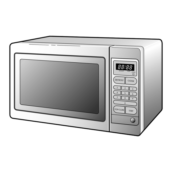
Page 5: Features Diagram
FEATURES DIAGRAM (MFM-6D) DEFROST COOK CLOCK DEFROST COOK STOP/CLEAR START & 1. Door latch–When the door is closed it will 9. Door screen-Allows viewing of food. automatically lock shut. If the door is opened The screen is designed so that light can pass while the oven is operating, the magnetron will through, but not the microwaves. - Page 6 FEATURES DIAGRAM (MFM-7DTP) Defront Cook Cook (Low) (Med) (High) Lock Time Or Alam On Defront Cook Cook (Low) (Med) (High) Lock Time Defrost Cook Cook (Low) (Med) (High) Or Alam On Defrost Cook Cook Porozen Beremeo Quick On (Low) (Med) (High) Reg Lag Soup...
-
Page 7: Installation
INSTALLATION 1. Steady, flat location This microwave oven should be set on a stady, flat surface. 2. Leave space behind and side All air vents should be kept a clearance. If all vents are covered during operation, the oven may overheat and, eventually, cause oven failure. -
Page 8: Operation Procedure
OPERATION PROCEDURE This section includes useful information about oven operation. Plug power supply cord into a standard 3- The oven door can be opened at any time pronged 15 Amp, 120V AC 60Hz power outlet during operation by touching the door release socket. -
Page 9: Controls
CONTROLS (MFM-6D) SETTING THE CLOCK When the oven is first plugged in, the display will flash ":0" and a tone will sound. If the AC power ever goes off, the display shows ":0" when the power comes back on. DO THIS... - Page 10 DEFROSTING When DEFROST is selected, the automatic cycle divides the defrosting time into periods of alternating defrost and stand times by cycling on and off. DO THIS... THIS HAPPENS... DEFROST The DEFROST indicator lights and “ :0” is displayed. 1. Touch DEFROST pad. DEFROST COOK The display will show the...
- Page 11 COOKING DO THIS... THIS HAPPENS... The COOK indicator lights and “ COOK :0” is displayed. 1. Touch COOK pad. DEFROST COOK The display will show the numbers you pressed in the order you touched. 2. Touch nunber pads for the cooking time.
-
Page 12: Defrosting And Cooking
DEFROSTING AND COOKING Some recipes require frozen foods to be thawed before cooking. This oven can be programmed to automatically defrost foods before cooking DO THIS... THIS HAPPENS... The DEFROST indicator lights DEFROST and “ :0” is displayed. 1. Touch DEFROST pad. DEFROST COOK The display will show the... - Page 13 DO THIS... THIS HAPPENS... When you touch START pad, the DEFROST and COOK indicator lights come on. START The DEFROST indicator light starts blinking to show you that the oven is in 5. Touch START pad. DEFROST mode. The display counts down the time remaining in DEFROST mode.
-
Page 14: Setting The Clock
CONTROLS (MFM-7DTP) SETTING THE CLOCK When the oven is first plugged in, the display will flash “:0” and a tone will sound. If the AC power ever goes off, the display will flash “:0” when the power comes back on. DO THIS... - Page 15 SETTING THE ALARM Your oven has an alarm clock feature. When the display shows the present time “:0”, set the alarm. DO THIS... THIS HAPPENS... ALARM Defrost Cook Cook The AM indicator lights and “ :0” (Low) (Med) (High) Lock Time is displayed.
- Page 16 THE COOKING (COOK HIGH) This basic microwave cooking method allows you to cook food for a desired time. Foods with high moisture content such as fish should be cooked on maximum power, as this is the fastest cooking method and best maintains the natural flavor and texture of the foods. DO THIS...
- Page 17 TIME COOKING (COOK MEDIUM) This basic microwave cooking method allows you to cook food for a desired time. Foods with medium moisture content such as beef should be cooked on medium power, as this is the fastest cooking method and best maintains the natural flavor and texture of the foods. DO THIS...
- Page 18 AUTO DEFROSTING (DEFROST LOW) When DEFROST is selected, the automatic cycle divides the defrosting time into periods of alternating defrost and stand times by cycling on and off. DO THIS... THIS HAPPENS... The DEFROST (LOW) indicator DEFROST(LOW) Defrost Cook Cook lights and “:0”...
- Page 19 QUICK-ON COOKING (HI-POWER) This simplified control lets you set and start micrwave cooking up to 5 minutes by just pressing 2 key pads. The power level is always set to HI (maximum power) for Quick-on cooking. Press the QUICK ON keypad until desired cooking time appears in the display. The QUICK ON key pad increases the cooking time by 30 second increments each time it is touched.
- Page 20 PRESETS Cooking with Preset allows you to cook or reheat many of your favorite foods by touching the appropriate Preset button. To increase cooking time touch preset button repeatedly until the correci cooking time appears on the display. DO THIS... THIS HAPPENS...
- Page 21 DO THIS... THIS HAPPENS... When you touch FROZEN FROZEN PIZZA Defrost Cook Cook PIZZA pad, “7” is displayed. (Low) (Med) (High) Lock Time Select pizza size as follows. 1. Touch FROZEN PIZZA pad. No Oz Alarm On FROZEN PIZZA ƒR ƒR 7oz: Touch FROZEN PIZZA once.
-
Page 22: Child Safety Lock
DO THIS... THIS HAPPENS... When you touch DINNER DINNER PLATE Defrost Cook Cook PLATE pad, “11” is displayed. (Low) (Med) (High) Lock Time 1. Touch DINNER PLATE pad. No Oz Alarm On DINNER PLATE ƒR ƒR 11oz: Touch DINNER PLATE once only. •... -
Page 23: Interlock Mechanism Functions And Adjustments
INTERLOCK MECHANISM FUNCTIONS AND ADJUSTMENTS The door lock mechanism is a device has been specially designed to completely eliminate microwave radiation when the door is opened during operation, and thus to perfectly prevent the danger resulting from the leakage of microwave. (1) Primary interlock switch When the door is closed, the hook locks the oven door. - Page 24 (2) Secondary interlock switch and interlock monitor switch When the door is closed, the hook pushes the push lever down ward, and push lever presses the button of the interlock monitor switch to bring it under "off", condition and presses the button of the secondary interlock switch to bring it under "on", condition.
-
Page 25: Measurement Of The Microwave Output Power
MEASUREMENT OF THE MICROWAVE OUTPUT POWER Microwave output power can be checked by indirectly measuring the temperature rise of a certain amount of water exposed to the microwave as directed below. 1) Microwave power output measurement is made with the microwave oven supplied at rated voltage and operated at its maximum microwave power setting with a load of 1,000±5cc of potable water. -
Page 26: Wiring Diagram
E) Measure the leakage by using microwave energy survery meter with dual ranges, set to 2,450 MHz. – Measured radiation leakage must not exceed the values prescribed below. • Leakage for a fully assembled oven with door normally closed must be less than 4mW/cm –... -
Page 27: Circuit Description
CIRCUIT DESCRIPTION Refer to the "WIRING DIAGRAM" Fig. 1 on page 25. MICROWAVE COOKING TIME COOKING 1. When the food is placed inside the oven and door is closed. 1) The low voltage transformer supplies the necessary voltage to the touch control circuit when the power cord is plugged in. - Page 28 OR FA H.V. CAPACITOR H.V. DIODE MAGNETRON WIRING COLOR OR: ORANGE H.V. TRANSFORMER Fig. 2 4. When the door is opened during cooking. 1) The primary interlock switch is opened to cut off primary voltage to the high voltage transformer to stop microwave oscillation.
-
Page 29: Safety Precautions For Disassembly And Repair
SAFETY PRECAUTIONS FOR DISASSEMBLY AND REPAIR – Cautions to be observed when trouble shooting. Unlike many other appliances, the microwave oven is a high-voltage, high-current equipment. It is completely safety during normal operation. However, carelessness in servicing the oven can result in an electric shock or possible danger from a short circuit. -
Page 30: Disassembly And Assembly
DISASSEMBLY AND ASSEMBLY 1. To remove cabinet. Remove three screws (F02). 2. To remove door assembly. 1) Remove two screws (F41) which secure the top hinge stopper (A03). 2) Remove the door assembly (A00) from top plate. 3) Reverse the above for reassembly. 3. - Page 31 (1) Remove the gasket door (A06) from door plate. (2) Remove the barrier screen inner (A05) from door plate. (3) Remove the door frame (A02) from door plate. (4) Remove the top hinge stopper (A03) from door plate. (5) Remove the spring (A08) and the hook (A07). (6) Remove the barrier screen outer (A01) from door frame (A02).
- Page 32 5. To remove control panel assembly. (1) Disconnect all the lead wires connected to control panel assembly. (2) Remove the screw holding the control panel assembly. NOTE: Do not attempt to remove switch membrane except for replacement. (1) Remove the three screws (B04) from the P.C.B. ass'y (B03). (2) Pull out the P.C.B.
- Page 33 6. To remove high voltage capacitor. (1) Remove the screw (F17) which secure the grounding ring terminal of H.V diode (F20) and the capacitor holder (F18). (2) Remove the H.V diode (F20) from the capacitor holder (F18). (3) Reverse the above steps for reassembly. High voltage circuit wiring MAGNETRON H.V.
- Page 34 CAUTION: Never install the magnetron without the metallic gasket plate which is packed with each magnetron to prevent microwave leakage. Whenever repair work is carried out on magnetron, check the microwave leakage. It shall not exceed 4mW/cm for a fully assembled oven with door normally closed.
-
Page 35: Trouble Shooting Guide
TROUBLE SHOOTING GUIDE Following the procedures below to check if the oven is defective or not. 1. Check grounding before checking trouble. 2. Be careful of the high voltage circuit. 3. Discharge the high voltage capacitor. (see page 28) 4. When checking the continuity of switches or of the high voltage transformer, disconnect one lead wire from these parts and then check continuity with the AC plug removed. - Page 36 3. Select AM or PM (excopt for pecects) 4. Prem Time or Alam 3. Press Stait 5. To shut off alam Press Alarm Stop Time Alarm Am/Pm STOP/CLEAR START Stop Alarm Start Clear Stop PCB Termination PCB Connector MFM-6D MFM-7DTP Fig. 7...
- Page 37 Fig. 8 Key Matrix (MFM-6D) Fig. 8 Key Matrix (MFM-7DTP) The membrane keyboard consists of 15 keys (MFM-6D), 25 keys (MFM-7DTP) whose configurations are described in Fig. 8 and provide 11 pad terminations to be connected to the touch control circuit as Fig. 7 3.
- Page 38 (TROUBLE 3) The oven does not operate at all; Display window does not display any figures and any inputs can not be accepted. Condition Result Cause Remedy Check Check continuity Replace Primary 15A fuse Malfunction of Continuity Interlock Switch Interlock Monitor blows Interlock monitor and Secondary...
- Page 39 Condition Result Cause Remedy Check Check continuity Outlet has Defective oven Replace of open proper Continuity thermostat thermostat Voltage Fuse does not open Check continuity Open power Replace of power supply Continuity supply cord cord. Defective touch Replace Normal control circuit Malfunction of Display do not Replace...
- Page 40 Condition Result Cause Remedy Check Turn table motor Check continuity Open winding Replace Continuity fan motor and of primary winding oven lamp turn of high voltage on for a transformer and Defective touch Replace Normal second when touch control control circuit the start pad circuit is tapped...
- Page 41 (TROUBLE 6) Microwave Output power is low. First of all, check if output power is really low following "measurement of the microwave output power" on page 24. Condition Check Result Cause Remedy Check the power Decrease in Output Lower than Customer source voltage power source...
-
Page 42: Component Test Procedure
COMPONENT TEST PROCEDURE 1. High voltage is present at the high voltage terminal of the high voltage transformer during any cooking cycle. 2. It is neither necessary nor advisable to attempt measurement of the high voltage. 3. Before touching any oven components or wiring, always unplug the oven from its power source and discharge the capacitor (see page 28). - Page 43 6. Interlock switches • You can test continuity of safety interlock and monitor switch by using ohmmeter. • The switch operation is checked by zero/unlimited. The meter should indicate zero resistance. • The sequence of check is interlock monitor switch, primary and secondary interlock switches check. 1) In case of interlock monitor switch check.
-
Page 44: Printed Circuit Board
PRINTED CIRCUIT BOARD 1. CIRCUIT CHECK PROCEDURE 1) Low Voltage Transformer (DMR-604P) Check. The low voltage transformer is located on the P.C.B. Measuring condition: Input voltage: 120V Frequency: 60Hz Voltage LOAD NO LOAD Terminal 6–7 8–10 2.4V 2.5V NOTE 1: Secondary side voltage of the low voltage transformer changes in proportion to fluctuation of power source voltage. - Page 45 3) Display problems CAUSE MEASUREMENT RESULT REMEDY Poor contact between Check the voltage Fix the PIN 1 & 25 P .C.B. and display of PIN 1 & PIN 25. 2.4 VAC filament. Defective Display Refer to "The display Replace P .C.B. trouble shooting data"...
- Page 46 Fig 9. Measurement Point...
- Page 47 CHECK METHOD POINT STAGE RELAY "2" ON –24VDC RELAY "2" OFF (2) When touching "START" pad, oven lamp turns on. Fan motor and turntable rotate and cook indicator in display comes on. * Cause: RELAY "1" does not operate. CHECK METHOD POINT STAGE RELAY "1"...
- Page 48 6) When the digital clock does not operate properly POINT WAVEFORM T: 16.67 ms -14V If clock does not keep exact time, you must check resistor R11, R17.
-
Page 49: Circuit Diagram
2. P. C. B. CIRCUIT DIAGRAM (MFM-6D) - Page 50 2. P. C. B. CIRCUIT DIAGRAM (MFM-7DTP)
-
Page 51: Component Information
3. COMPONENT INFORMATION 1) Transistor Q1-5 Emitter Collector Base 2) Diode and Zener Diode DIODE Cathode (K) ANODE (A) D1-7, 8-14 ZENER Cathode (K) ANODE (A) ZD1-3 DIODE... -
Page 52: Printed Circuit Board
4. PRINTED CIRCUIT BOARD... -
Page 53: Location No
CONNECTOR WAFER YW396-05VA 3519150510 CONNECTOR WAFER YW396-02V 3519150520 DIGITRON SVM-5MS06 DSVM5MS06-1 HOLDER VFD NYLON66 351300500 PCB MAIN M145 M145-1 3514311351 TRANS POWER LVT1 DMR-604P 5EPU041403 RELAY RY1,3 G5J-1-TP-M24V 5SC0101107 RELAY G5B-1 (DC24V) 5SC0101109 IC MICOM HD404314B47S 147S811F00 MFM-6D HD404314D13S 147S818F00 MFM-7DTP... -
Page 54: Exploded And Parts List
EXPLODED AND PARTS LIST 1. Door Assembly DOOR ASSEMBLY: 3511706402 REF. NO PART CODE PART NAME DESCRIPTION Q'TY REMARK 3517003100 BARRIER-SCREEN *0 PMMA T0.5 3512202200 FRAME DOOR ABS HR-401 H-2938 3515201500 STOPPER HINGE *T AS KOR-61150S 3511706520 DOOR PAINTING AS KOR-81250S 3517002900 BARRIER-SCREEN *I... - Page 55 2. Control Panel Assembly CONTROL PANEL ASSEMBLY: PKCPSWR100 (MFM-6D) PKCPSWWK00 (MFM-7DTP REF. NO PART CODE PART NAME DESCRIPTION Q'TY REMARK 3518517540 KOR-811F2A MFM-6D SWITCH MEMBRANE 3518517550 KOR-811F3A MFM-7DTP 3516713410 CONTROL-PANEL ABS AF-345 HF-700HT PKMPMSR100 KOR-811F2A MFM-6D PCB MAIN AS PKMPMSWK00...
- Page 57 REF. NO PART CODE PART NAME DESCRIPTION Q'TY REMARK DOOR AS See Exploded and Part List CONTROL-PANEL AS 3510801400 CABINET PCM T0.6 7112401011 SCREW TAPPING T1 TRS 4x10 MFZN 3516105640 CAVITY AS KOR-811F2A 7122401211 SCREW TAPPING T2S TRS 4x12 MFZN 7122401211 SCREW TAPPING T2S TRS 4x12 MFZN...
- Page 58 DAEWOO ELECTRONICS CO., LTD. 686, AHYEON-DONG, MAPO-GU, SEOUL, KOREA. C.P.O. BOX 8003 SEOUL KOREA TELEX: DWELEC K28177-8 FAX: (02) 360-8184 TEL: (02) 360-8183 S/M NO.: R821M AM012 PRINTED DATE: JUN. 1998...
Need help?
Do you have a question about the MFM-6D and is the answer not in the manual?
Questions and answers