
Related Manuals for Coldelite UF-253E Gravity and Pump


Summary of Contents for Coldelite UF-253E Gravity and Pump
-
Page 1: Operation Manual
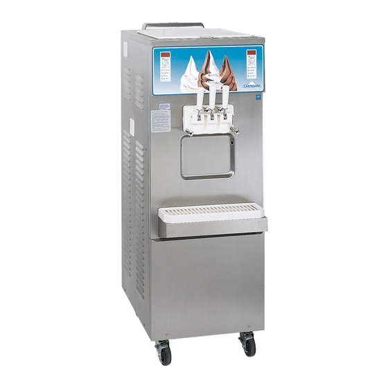
• • • P.O. Box 4069 Winston-Salem, NC 27115 336-661-9893 336-661-9895 (Fax) UF – 253 E Gravity and Pump Soft Serve Freezer Double Flavor Floor Model OPERATION MANUAL... - Page 2 Thank you for selecting Coldelite to meet your operation and growing demands. Your Coldelite freezer has been manufactured utilizing the most advanced technology and modern equipment available in the industry. We at Coldelite, take great pride and care in the manufacturing of each and every freezer, using only the finest components available, to provide you with many years of trouble free operation.
-
Page 3: Table Of Contents
Index Foreword Page # Part I Installation A) Uncrating B) Positioning the Machine C) Electrical Requirements D) Completing the Installation Part II Explanation of Controls A) Electronic Control Panel B) Dispensing Handles C) Proximity Switches D) Dispensing Head Safety Switch E) Electric Control Panel F) Other Controls Part III... -
Page 4: Part I Installation
Failure to closely follow operational and airflow. maintenance procedures may result in damage to the unit and / or void your warranty. Coldelite Corporation will not be responsible for any machine not properly operated or maintained. Part I – Installation... -
Page 5: C) Electrical Requirements
NOTE: Always turn the machine OFF and disconnect the power supply switch to the freezer All Coldelite machines are equipped with step down prior to exposing any electrical connections or transformers for the control circuit supply. These moving parts. -
Page 6: Part Ii Explanation Of Controls
following machine modes: Part II – Explanation of Controls - Automatic - Stand-by A) Electronic Touch Pad – (Refer to figure 4) - Beater The indicator light will illuminate corresponding to the mode selected with the touch pad. Automatic Mode When placed in this mode the indicator light L2 will illuminate and the machine will start the freezing STOP... -
Page 7: B) Dispensing Handles
The electrical control panel is located on the bottom of the front panel. This control panel contains all of the machines electrical control components. ONLY a Coldelite Authorized Technician should access this control panel. !! IMPORTANT WARNING !! Disconnect the freezer power supply before... -
Page 8: F) Other Controls
3) Beater Motor Overload Protector - (Left/Right) – Monitors the current draw of the beater drive motor. If the motor draws excessive amperage, the overload will trip and Alarm 1 (RtA) will be displayed on the touch pad monitor. 4) Main Transformer – This transformer reduces the incoming line voltage to 24 volts for the primary control circuit. -
Page 9: Part Iii Initial Cleaning Procedure
Next remove the outer regulating sleeve from the Part III–Initial Cleaning Procedure center tube by pulling straight off. !! IMPORTANT !! Before starting this procedure, place the machine in the STOP mode on the touch pad. This is a new machine and although clean, it must be completely disassembled, washed and sanitized before adding fresh product. -
Page 10: B) Pump Fed Cleaning Procedure
Pump Fed Machines Disassemble the mix pump assemblies as pictured below (one per side). When disassembling the orings from the other components, use only the Proceed with the disassembly of the mix injection oring removal tool provided in the spare parts tool pumps located in each mix storage tank. -
Page 11: C) Disassembling The Dispensing Head
Pull the handle-retaining rod out far enough to C) Disassembling the Dispensing Head allow the handle to disengage. Loosen and remove the four dispensing head- retaining knobs. The knobs are removed by turning counter clockwise until loose. Return the retaining rod to its original position. Using the metal rod as a base, lever the piston from the dispensing head with the handle. -
Page 12: D) Disassembling The Beaters / Augers
Remove the three scraper blades from the beater / D) Disassembling the Beaters / Augers auger frame by gently rotating the blade out of the frame support brackets. Remove the beaters / auger assemblies from each cylinder by pulling straight out of the machine towards you. -
Page 13: Part Iv Assembling The Freezer
Install the idler into the beater frame by placing it Part IV - Assembling the Freezer through the end pusher. Assembling the Beater / Augers After completing the Cleaning Operation, you are now ready re-assemble the freezer. First locate the parts needed to assemble both beater / auger assemblies. -
Page 14: B) Assembling The Dispensing Head
Insert both beater assemblies into the freezing B) Assembling the Dispensing Head cylinders. Holding the beater horizontal, gently slide it straight into the cylinder until it can go no Locate the parts that will be needed to assemble the farther. dispensing head. - Page 15 Once the orings have been installed onto the three Turn over the dispensing head and insert the two pistons, place a bead of lubricant between the large orings into the grooves in the dispensing orings. head. Lightly lubricate the outside of these orings. Spread the lubricant to lightly coat the piston surface between and including the orings.
-
Page 16: C) Assembling The Gravity Feed Tubes
You are now ready to install the dispensing head C) Assembling the Gravity Feed Tubes assembly onto the front of the freezer. Locate the parts needed to assemble the gravity feed tubes. This should include: A) Splash guard, B) Orings (2per), C) Outer regulating sleeve, D) Center gravity feed tube Next, slide the two orings onto the center gravity feed tube oring grooves. -
Page 17: D) Assembling The Mix Injection Pumps
Insert the splash guards into the top hole of the First install the small oring (#1197) onto the pressure gravity feed tube. relief plunger (#105) and lightly lubricate the oring. NOTE: Oring #1126 is slightly smaller than the other orings used on this assembly. Locate these Lightly lubricate both orings on each tube with the orings first and install. - Page 18 To assemble the mix pumps, first locate the pump Assemble the plastic suction tube (#271) by gears (#38&A) and pump body (#39). Lightly installing the oring (#1126) into the groove and lubricate the top, bottom, and inside bore of the lightly lubricate.
-
Page 19: Part V Sanitizing The Freezer
With the dispensing handles closed, pour an even Part V - Sanitizing the Freezer amount of the sanitizer solution into both mix tanks. With the large cleaning brush, clean all Prior to filling the machine with fresh liquid mix, surfaces of the mix storage tanks with the the assembled machine must be sanitized. - Page 20 Place the clean pail under the dispensing head and “Push to Select” button on the front touch pad pull the handles, allow the sanitizer to completely (#571.2) until the beater mode is selected. Allow drain from the freezer. the machine to run in the beater mode for After the sanitizer has completely drained, close the approximately 10 seconds then push the “Stop”...
-
Page 21: Part Vi Starting The Freezer
Set to the closed position (bottom) and replace the Part VI – Starting the Freezer splash guard. You may now start the freezing process by pressing Only after completing the cleaning and sanitizing the “Select” button (#571.2) and selecting the procedures should you fill the machine with fresh Automatic mode. -
Page 22: B) Pump Fed Machines
With the mix tanks filled with liquid mix and the A) Pump Fed Machines elbows connected to the pumps, you can now prime the cylinders. To prime the cylinders, press the With your clean, sanitized hands, install the feeding “Select” button on the touch pad, selecting the elbows into the cylinder feed holes. -
Page 23: Part Vii Operating The Freezer
Dispense the product without exceeding the Part VII – Operating the Freezer freezers production capacity. If you do not exceed this pace and are careful to refill the machine with The machine will automatically stop the freezing fresh mix, you can be sure you will rarely have to process after achieving the pre-set “consistency”... -
Page 24: B) Gravity Fed Machines - How To Operate And Make Adjustments
B) Gravity Fed Machines C) Pump Fed Machines-Operation The gravity feed tube consists of two tubes, one The mix injection pump runs whenever the beater sliding inside of the other, and a center splash drive motor is turning. To regulate the amount of guard. -
Page 25: Part Viii Periodic Cleaning Procedures
With the machine still in the Beater mode, place a Part VIII – Periodic Cleaning pail under the dispensing head. Slowly pull the two Procedures end handles and allow all of the product to drain from the machine. Cleaning and sanitizing schedules for your freezer are determined by your local Health Department and / or Department of Agriculture and must be followed accordingly. -
Page 26: B) Pump Fed Machines
Prior to draining the last time, brush clean all B) Pump Fed Machines surfaces of the mix storage tanks with the cleaning brushes provided with the freezer. With frozen mix in the cylinders, select the Beater mode on the front touch pad by pressing the Push to Select button (#571.2) until pilot light #L4 illuminates. - Page 27 Remove the feeding elbow assemblies from each Press the Push to Select button on the front touch mix tank by first sliding the connecting tube away pad (#571.2), and carefully select the Beater mode. from the pump cover, Then turn the elbow assembly Allow the machine to run for 1 –...
-
Page 28: Part Ix Technical Information A) Refrigeration
You are now ready to disassemble and clean your C) Proximity Switches freezer. Please refer to Part III – Initial Cleaning The sensitivity of these switches can be adjusted Procedure of this operation manual for instructions with a small screwdriver. The trimmer location is on how to proceed. -
Page 29: Part X Maintenance
32 degrees F. Before storing at a temperature below 32 Your Coldelite freezer has been designed, degrees you must remove all liquids from the engineered, and manufactured to achieve high per- freezer and winterize the water condenser coil. -
Page 30: A) Troubleshooting Guide
Contact a Coldelite Authorized Service Technician 5) Machine Runs Continuously a) Restricted air flow (Air Cooled) a) Clean air condenser or contact a Coldelite Authorized Service Tech. b) Low on refrigerant b) Contact a Coldelite Authorized Service Technician c) H.O.T. setting too high for product used c) Set the H.O.T. - Page 31 Contact a Coldelite Authorized Service Technician 5) Machine Runs Continuously a) Restricted air flow (Air Cooled) a) Clean air condenser or contact a Coldelite Authorized Service Tech. b) Low on refrigerant b) Contact a Coldelite Authorized Service Technician c) H.O.T. setting too high for product used c) Set the H.O.T.
- Page 32 B) Machine Safety Alarms This freezer is equipped with built in, self monitoring (Safety) devices, which will interrupt operation of the freezer if activated. When activated, the little red LED light at the bottom right corner of the display monitor will illuminate and flash. (refer to Figure 12) This LED will flash when the alarm has been activated.
Need help?
Do you have a question about the UF-253E Gravity and Pump and is the answer not in the manual?
Questions and answers