
Related Manuals for Coldelite UC-113G/B


Summary of Contents for Coldelite UC-113G/B
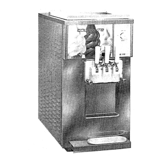
- Page 1 UC-113G/B Soft Serve Freezer D O U B L E F L A V O R C O U N T E R MODEL OPERATION & SERVICE 3760 Industrial Drive, Winston-Salem, NC 27105 Telex: .Telephone:. (91 9) 661-9893 Telefax: (9.1 9) 661 -9895'...
-
Page 3: Page Foreword
Thank you for selecting Coldelite to meet today's fast growing demands. Your Coldelite freaer has been manufactured at one of the most modem freezer manufacturing plants in the USA., our Lodi, New Jersey facility, utilizing the most advanced equipment and technology available in the industry. -
Page 5: Table Of Contents
Page ............FOREWORD ........INSTALLATION PART I ..........A) Uncrating ......B) Positioning the Machine C) Machines Equipped with Water Cooled Condensers ......D) Electrical Requirements ......E) Completing the Installation ..... PART II EXPLANATION OF CONTROLS ........A) The Selector Switch ...... -
Page 7: Installation
Failure to closely follow operational and maintenance procedures may result in damage to the unit and/or void your warranty Coldelite Corporation will not be responsible for any machine not properly maintained In the event this unit should malfunction, please contact your... -
Page 8: D) Electrical Requirements
Coldelite freezers are equipped with protection for the beater T o maintam a head pressure of 220 psi 2 psi, while the motor Should the line voltage drop, or in the unlikely event a compressor is running, attach a refrigeration high pressure... -
Page 9: E) Completing The Installation
PART I! In all installations, the machine must be properly grounded Since all high voltage components (controls are 24 volts) are EXPLANATION connected by means of flexible conduit, adequate ground continuity is assured by running and fastening a ground line to CONTRQLS the machine junction box ground lug (Ref Fig 5 ) After electrical connections are completed, check the rotation... -
Page 10: Low Mix Level Indicator
with the level of mix The plastic float contains a magnet 3) ENERGY CONS Th~s posit~on is used during prolonged, which will energize or close the mix level switch at a factory idle periods. The temperature of the product in both the mix pre-set position Once closed, the mix level switch energizes tank(s) and freezer cylinder(s) is held at a safe temperature the "low mix level indicator"... -
Page 11: E) Other Controls
Beater Motor Electronic Solenoid H..O. M Relay Starter Terminal Block Compressor Timer Volt Contactor ( 220 Overload safety Terminal Block Protector Thermostat Volt Mix TankThermostat Transformer Current Energy Cons.Thermostat Transformer The following is an explanation of the control panel controls; 9) The main TRANSFORMER steps down the line voltage (220 volts) to 24 volts for the control circuit I ) COMPRESSOR CONTACTOR... -
Page 12: Part Ill
HELPFUL SUGGESTION: Before proceeding with the 2) The HIGH PRESSURE CUT-OUT is located on the right side disassembly of the freezer, we recommend a plastic dish of the freezer and is tied into discharge or high side line pan be used in which to place the parts This will minimize near the compressor In the event of high pressure situation, the possibility of misplacing or damaging the various it will shut down the compressor Reset is automatic when... - Page 13 "SLEEVE" 4) Loosen and remove the four (4) dispensing head retaining Next, remove the gravity tube by pulling it straight the tube off of knobs The knobs are removed by turning in a Counter., clockwise direction. Finally, remove the o-rings using the O-RING EXTRACTOR included in the "start-up kit"...
- Page 14 Using the O-RING EXTRACTOR, remove the piston o-rings 6 ) Disassemble the dispensing head by first opening all the Each piston o-ring groove notched for easy insertion of dispense handles the o-ring extractor Turn the dispensing head over and remove the two large o- rings from the back of the head.
- Page 15 10) Wash all the parts in luke warm water (80" 85°F) using a 8) Disassemble the beaterlauger by first removing the rubber mild detergent and the cleaning brushes provided in the beater shaft (lip) seal, simply slide it off the shaft. START-UP KIT DO NOT USE HOT WATER O N ANY OF TWE PLASTIC PARTS AS DAMAGE TO THE PARTS CAN RESULT...
-
Page 16: Assembling The Freezer
Push the idler back, inserting its shaft into the hole of the PART IV beaterlauaer shaft ASSEMBLING THEFREEZER Once the parts have been washed, rinsed and sanitized, the freezer is ready to be re-assembled Prior to beginning the re- assembly procedure, sanitize your hands by submerging in the sanitizing solution Begin to re-assemble as follows: A) Assembling the Beater/Augers When installed correctly, the idler (when turned) should rotate... -
Page 17: Assembling The Dispensing Head
Rotate the beaterlauger until you feel the drive shaft engage 5 ) Repeat the above procedure for the second beaterlauger and ~ u s h the beaterlauaer further back to properly seat assembly. 6) Finally, insert the beaterlauger into the freezer cylinder Holding the beaterlauger hor~zontally, slide it straight into the cylinder until it can go no further IMPORTANT: Before installing the beaterlauger, make certain... - Page 18 5 ) Insert the two end pistons into the two end chambers of 2) First, remount the end piston O-rings onto the end pistons the dispensing head body making certain to align the Simply roll onto the piston until they drop into the O-ring square notch of the piston with the rectangular notch at notches.
-
Page 19: C) Assembling The Gravity Feed Tubes
HAND TIGHTEN the knobs in a crisscross manner as 7) Affix the dispensing head to the machine Lift the front shown below micro switch activating lever and slide the dispensing head onto the four mounting studs Release the activating lever, the lever should rest vertically atop the pistons C) Assembling the Gravity 8) Install the dispensing handles Insert the round lobe of the... -
Page 20: Sanltlzlng The Freezer
7) Install the two (2) mix level floats by simply sliding one each 3) Slide the sleeve onto the tube Please note that the slots in onto the stainless steel shaft in the mix tank the sleeve should be at the top of the tube when installed.. Slide the splash guard into the tube. - Page 21 Turn the selector switch to the "OFF" position Mix the sanitizer (2 ounces of Steera Sheen green label or equivalent) into a clean pail containing two gallons of warm water This solution will make a 200 P M (parts per million) concentration of chlorine sanitizing solution.
-
Page 22: Starting The Freezer
2) Rest the gravity feed tubes upright against the side of mix 7) Allow the sanitizer to completely drain Close handles tank as shown 3) Pour 1% pints of mix into each mix tank. Allow the mix to drain into the freezer cylinders. This will properly "prime" each cylinder HELPFUL SUGGESTION: When the sanitizer stops flowing, leave the handles open and turn the selector switch to the... -
Page 23: Operating The Freezer
Turn the selector switch to the "AUTO" position 5)Turn the adjustment sleeve of the gravity tube until the medium sized hole for moderate production is aligned with the hole in the gravity feed tube Mln~mum Moderate Max~mum Energy Prcduct~on Product~on Prcductlon Conservatton Figure 12... -
Page 24: Routine, Periodic Cleaning
When the portion is the size you want, close the handle and The outer tube is actually a valve Rotating it from hole to hole pull the cup or cone straight down to add a peak on the outer tube varies the size of the hole and the amount of mix that flows into the freezing cylinder The size of the air inlet, at the top of the tube, does not change so the amount of air that enters the freezing cylinder is constant... - Page 25 When the product has stopped flowing, turn the Selector Remove the Gravity Feed Tubes Pull the tubes straight up Switch to the OFF position Close the spigot handle and out 5 ) Fill hopper(s) and cylinder(s) with cold water (a mild, non- foaming dish washing detergent is recommended) 2) Turn the Selector Switch to BEATER position and let the machine run for...
-
Page 26: Technical Information
Voltage 208-230V 1) Adjusting Product Temperature Coldelite uses a Hard-0-Matic system which is referred to as H 0 M. This electronic device controls the refrigeration system for the freezing cylinder by 'sensing' the consistency or hardness of the product inside the freezing cylinder No thermostats are... -
Page 27: C) Drive System
Overload Protector Calibration PART X T25DU 7.5/11 8 Amps UC-113G MAINTENANCE Energy conservation Your COLDELJTE machine has been designed, engineered and Models equipped with this feature allow the operator to manufactured to achieve high performance and long durability switch to a more economical circuit during limited service The life expectancy of a machine, any machine, does not During this mode of operation, the product and hopper depend only on the quality of its components and design, but... -
Page 28: A) Trouble Shooting Guide
TROUBLE SHOQTWG GUIDE Problem Possible Cause Suggested Remedy a) Drawing faster than machine can a) Slow down draw rate 1) Product too soft produce b) Contact authorized service agency b) H 0 M control out of calibration or c) Contact authorized service agency malfunctioning c) Machine short of freon gas a) No mix or low mix in mix tank... -
Page 29: Wiring Guide
WIRING DIAGRAM Overload Protector Beater Motor Beater Motor Rotary Selector Switch Energy Cons Thermostat Compressor Motor Cylinder Solenoid Valve Mix Tank Thermostat Front Microswitch Mix Tank Solenoid Valve l T A Beater Motor Contactor Fan Motor Magnetic Switch Mix Level l T C Compressor Contactor Pressure Control... - Page 30 Figure A Description Code No. Code No. Description Retaining knob for dispense head Front decal std. color 1780350* 1654200 Left side panel Volt Bulb for mix fill indicator 1902220 030* Right side panel CapILense Orange 19032 171 1150 Upper rear panel water cooled models 17201 7 1 * Knob for selector switch...
- Page 31 IDENTBFICATION PARTS 1785040 Figure B Code No. Description Code No. Description Ring spacer, trans. Rubber beater. lip seal 161 5020 1411 190 1615130 Ring nut, trans. housing Gear box seal Seal, dr~ve shaft 1616020 1518170 Snap ring 1618270 Flywheel Snap ring 1518180 Gravity feed tube Bushmg for tension arm...
-
Page 32: C) Parts Identification
PARTS IDENTIF1CATION 1641600 Figure C Code No. Description Code No. Description Idler, for "2E" beater Beater seal 1641 600 141 1190 End pusher, for "2E beater "2E" Beater, seal 1642070 1640400 " Figure D Code No. Description Description Code No. Center piston O-ring 1653270 141 1240... - Page 33 PARTS IDENTIFICATION Figure Code No. Description 1680080 Nylon pin, front micro cam 1680260 Adjustment screw, front micro Cam, front micro switch 1 6801 20 1 680300 Activating lever, front micro 1680230 Pivot shaft, front micro cam 1720260 Microswitch, Burgess e BR 35 18080 Snap ring Figure...
- Page 34 Figure H Description Code No. Description Code No. Terminal block, 220V (individual block) Relay, mini-mod 55/34 24 Volt 171 1520 1724620 Terminal block, 24V (individual block) 1724680 Overload, 7.511 1 Amp. 171 1530 Thermostat, Danfoss Timer, fiber 24 Volt 17251 10 17231 00 Hard-o-matic torque control, electronic 24 Volt Transformer, Dongan 230/24V...
Need help?
Do you have a question about the UC-113G/B and is the answer not in the manual?
Questions and answers