Table of Contents
Advertisement
Advertisement
Table of Contents

Subscribe to Our Youtube Channel
Related Manuals for ZDC ZN-7100-DE500-G

Summary of Contents for ZDC ZN-7100-DE500-G
-
Page 1: User Manual
ZN-7100-DE500-G Outdoor Wireless Access Point User Manual Version: 1.0... -
Page 2: Table Of Contents
Table of Contents Table of Contents Chapter 1 Product Overview ........... .1 Introduction........................ - Page 3 Table of Contents Chapter 5 Configuring the Wireless Access Point ....... . .28 General Menu......................
-
Page 4: Federal Communication Commission Interference Statement
Federal Communication Commission Interference Statement This equipment has been tested and found to comply with the limits for a Class B digital device, pursuant to Part 15 of the FCC Rules. These limits are designed to provide reasonable protection against harmful interference in a commercial environment. -
Page 5: About This Manual
About This Manual This user manual is intended to guide professional installers in installing and configuring the ZN-7100-DE500-G wireless access point, and in building the infrastructure centered on it. It includes procedures to assist you in avoiding unforeseen problems. -
Page 6: Product Overview
(MIMO-OFDM) modulation techniques. Supporting a maximum data rate of 300Mbps per single band and equipped with optical interfaces, the ZN-7100-DE500-G is capable of high transfer rates, receiver sensitivity and long transmission distance, making it an ideal solution for broadband Last Mile services and hotspot backhauling. -
Page 7: Package Contents
Package Contents Package Contents ZN-7100-DE500-G Wireless Access Point Pole Mount Clip and Bracket Pole Mount Securing Rings Locking Nut and Sealing Cap Screw Kit 48VDC Power Adapter + Power cord W a r r a n t y C a r d... -
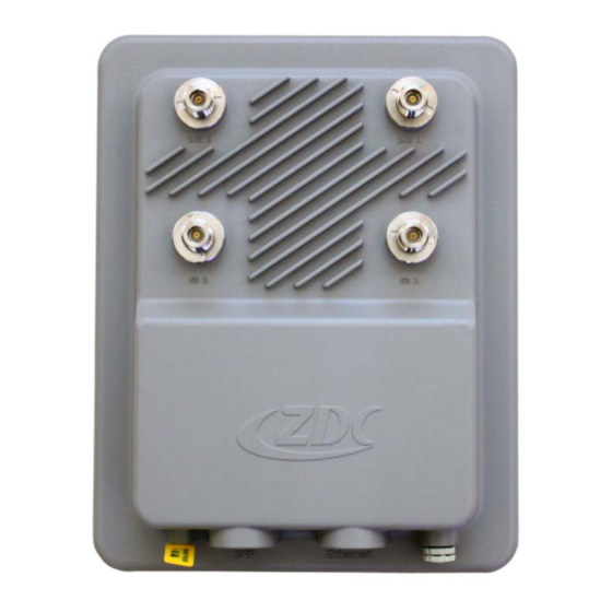
Page 8: Product Views
Product Views Product Views Top View Figure 1-1. ZN-7100-DE500-G Top View Table 1-1. ZN-7100-DE500-G Top View Item 2.4GHz RF Antenna Connector 2.4GHz RF Antenna Connector 5GHz RF Antenna Connector 5GHz RF Antenna Connector Bottom View Figure 1-2. ZN-7100-DE500-G Bottom View... -
Page 9: Led Definitions
LED Definitions Table 1-2. ZN-7100-DE500-G Bottom View Item Ethernet Reset Button Ventilation Hole LED Definitions Figure 1-3. LED Indicators on the PoE Injector Table 1-3. LED Definitions Name State Description Power is supplied to the device through On (green) the Ethernet port. -
Page 10: Safety Information
Safety Requirements Chapter 2 Safety Information Safety Requirements Before you begin installing the device, read through the following safety guidelines to prevent personal injury or property damage. Seek assistance from a trained professional installer, especially if it is your first time to install this device. -
Page 11: Grounding Requirements
Installation Precautions protection system apart from any electrical grounding device and lightning protection system as far as possible. Keep the device far from high-power radio transmitter, radar transmitter, high-frequency, and high-current devices. Grounding Requirements Make sure to provide an excellent grounding system to guarantee the stable operation of device, as well as to protect it from lightning, interference and electrostatic discharges. -
Page 12: Installing The Wireless Ap
Before Installation Chapter 3 Installing the Wireless AP Before Installation If it is your first time to install an AP device, we recommend seeking assis- tance from a trained professional who is knowledgeable in radio frequency (RF) and related local regulations. Only use the power cord and included parts that came with the device to pre- vent damage to the device or injury to personnel. -
Page 13: Determining The Optimal Mounting Location And Orientation
Before Installation Obstructions, building materials, and sources of interference: Make sure that the installation area has as few physical obstructions as possible. Tall buildings, trees or concrete pillar may block wireless communication, so avoid installing areas that may pose difficulties to radio signal penetration. Determining the Optimal Mounting Location and Orientation The installation location and orientation are critical factors in the performance of the access point. -
Page 14: Waterproofing The Outdoor Lan Cable
Waterproofing the Outdoor LAN Cable Waterproofing the Outdoor LAN Cable For outdoor installation, you need to waterproof the LAN port using the sup- plied sealing cap. 1. Slide the locking nut over the bare end of the Ethernet cable. 2. Slide the sealing cap over the bare end of the Ethernet cable. 3. -
Page 15: Hardware Installation
Hardware Installation Hardware Installation Mounting on a Pole Note: Make sure that the pole for installation is securely attached to a solid, stable base. 1. Secure the mounting clip to the back of the wireless AP with four screws. 2. Slide the securing rings through the mounting bracket. Adjust the straps to make sure that the rings are securely fastened to the pole. -
Page 16: Installing Antennas
Connecting to a Power Source Installing Antennas You may install optional 2.4 or 5GHz antennas on top of the wireless AP to extend the range of your wireless network. Caution - Make sure that you disconnect the wireless AP from the power source before connecting the optional antennas. - Page 17 Connecting to a Power Source 5. Connect an Ethernet cable between the wireless AP controller and the com- puter. 6. Connect a power cord to the PoE injector. 7. Connect the power plug to a wall socket. Wall Socket Power Plug Power Cord PoE Injector Wireless AP...
-
Page 18: First-Time Connection And Configuration
First-Time Connection and Configuration First-Time Connection and Configuration Connecting to a PC 1. Connect one end of an RJ-45 cable to an Ethernet port on your computer. 2. Connect the other end to the LAN/PoE port on the wireless AP. Note: Make sure all other components and hardware are properly connected and installed. -
Page 19: Connecting The Wireless Ap To Your Network
First-Time Connection and Configuration Note: If the following message appears, click Continue to this website to open the Access Portal. Figure 3-6. Security Certificate Warning 5. Enter the following default credentials. Username: admin Password: password 6. Click Login to enter the Access Portal main page. 7. - Page 20 First-Time Connection and Configuration 8. If you want the wireless AP to obtain the address from the DHCP Server auto- matically, select DHCP Client. Figure 3-7. Basic Setup > Configure AP as > DHCP Client 9. If you want to manual set up your network’s configurations, select STATIC. 10.
-
Page 21: Changing The Default Password
First-Time Connection and Configuration Note: Make sure that the wireless AP and your PC are in the same subnet. Figure 3-8. Basic Setup > Configure AP as > STATIC Changing the Default Password The first time you log in to the Access Portal, you will be prompted to change the default password. -
Page 22: Accessing The Wireless Ap
Setting Up the Access Portal Chapter 4 Accessing the Wireless AP Setting Up the Access Portal Manage the wireless AP easily using a web browser. 1. Open the Web browser and type the IP address of the smart antenna into the address field. -
Page 23: Navigating The Access Portal
Navigating the Access Portal Note: If the following message appears, click Continue to this website to open the Access Portal Figure 4-2. Security Certificate Warning 2. Enter the username and password. Note: The administrator may have changed the default credentials. Obtain the username and password from your administrator. - Page 24 Navigating the Access Portal 1. Quick Management Action Bar The quick management action bar provides three useful links: Home, Help and Exit. Figure 4-3. Quick Management Action Bar Table 4-1. Quick Management Action Bar Item Description Returns to the main interface, which displays general information Home about the wireless AP.
-
Page 25: Main Menu
Navigating the Access Portal 2. Main Menu This area contains all the configuration parameters of the wireless AP. There are seven main menus. Figure 4-4. Default Home Page with Main Menu Table 4-2. Main Menu Item Description Displays basic information about the wireless AP: ... - Page 26 Navigating the Access Portal Figure 4-4. Default Home Page with Main Menu Table 4-2. Main Menu (Continued) Item Description Lets you modify default values for basic settings, such as AP mode, user name, AP name, Ethernet data rate, link integrity and QoS class mode.
-
Page 27: Factory Default Settings
Factory Default Settings 3. Configuration Window This area displays the submenus for the Configuration menu. Figure 4-5. Configuration Window Factory Default Settings Table 4-3. Factory Default Settings Item Default Value Username admin Password password Card Index Card1 Accessing the Wireless AP... - Page 28 Factory Default Settings Table 4-3. Factory Default Settings (Continued) Item Default Value AP Mode Fat AP APxxxxxx (xxxxxx repre- Access Point Name sents the last six digits in the wireless AP MAC address) Ethernet Data Rate Automatic Link Integrity Disable QoS Class Mode None IP Mode...
- Page 29 Factory Default Settings Table 4-3. Factory Default Settings (Continued) Item Default Value Enable Radio Austria (Country domain Country/Region may vary) Operating Mode AP Mode Wireless Standard 802.11b/g/n Basic Speed 1/2/5.5/11 Support Speed 6/9/12/18/24/36/48/54 Channel/Frequency 6/2.437GHz Data Rate Auto RTS Threshold 2346 Beacon Interval DTIM Time Interval...
- Page 30 Factory Default Settings Table 4-3. Factory Default Settings (Continued) Item Default Value Primary IP Address: 0.0.0.0 Port Number: 1812 Shared Secret: Null Authentication/Access Control RADIUS Server Secondary IP Address: Configuration 0.0.0.0 Port Number: 1812 Shared Secret: Null RADIUS Settings Reauthentication Time 3600 Primary IP Address: 0.0.0.0 Port Number: 1813...
- Page 31 Factory Default Settings Table 4-3. Factory Default Settings (Continued) Item Default Value Use Time Server (GMT+08:00) Beijing, Time Zone Chongqing, Hong Kong, Urumqi Time Setting Null Flow Balance Mode Disable Enable VoIP Control Enable Ping Test Enable ART Test Mode Advanced Setup Enable DHCP Snooping Enable IGMP Snooping...
- Page 32 Factory Default Settings Table 4-3. Factory Default Settings (Continued) Item Default Value Firewall function Close IP Filter IP address filtering function Close The default filter rule Accept all Firewall function Close MAC address filtering func- MAC Filter Close tion The default filter rule Accept all SysLog Enable Syslog...
-
Page 33: Configuring The Wireless Access Point
General Menu Chapter 5 Configuring the Wireless Access Point General Menu On the main menu, go to General to view information about the system and the wireless access point. Figure 5-1. General Menu Table 5-1. General Menu Item Description Displays information about the device model, memory capacity, System Information memory usage, CPU usage, flash usage, device temperature, AP uptime, and Ethernet port status. -
Page 34: Current Ip Settings
General Menu Table 5-1. General Menu (Continued) Item Description Displays the wireless AP name, MAC address, country/region, Access Point firmware version, hardware version, bootloader version, and man- Information agement VLAN ID Displays the IP type, IP address, subnet mask, and default gate- Current IP Settings way. -
Page 35: Advanced Setting
General Menu 6. To use the L2 protocol to discover the thin AP, select Connect with Wireless Switch via L2 Discovery. Figure 5-2. Wireless Switch Settings Advanced Setting Configuring Fat AP Mode Before configuring fat AP Basic settings, make sure that AP mode is set to Fat 1. - Page 36 General Menu 3. Click Enable on Reboot, then click Apply. The wireless AP reboots and will be operate in thin AP mode the next time you log in. Figure 5-4. Selecting AP Mode Configuring Thin AP Settings Before configuring thin AP Basic settings, make sure that AP mode is set to Thin AP.
-
Page 37: Viewing The System Log
General Menu Viewing the System Log The system log page displays event log Information of the AP. 1. On the main menu on the left, click SysLog. 2. Click Refresh to update the current statistics, or click Save As to save the log information as a file. -
Page 38: Basic Setup Menu
Basic Setup Menu Basic Setup Menu On the user interface menu, go to Basic Setup and configure these basic parameters. Figure 5-7. Basic Setup Menu Table 5-4. Basic Setup Menu Item Description AP Mode Select either Fat AP or Thin AP. User Name Change the user name. -
Page 39: Configuring The Ap As A Bridge
Basic Setup Menu Table 5-4. Basic Setup Menu (Continued) Item Description Enable or disable the Spanning Tree Protocol, which can prevent Spanning Tree network loops and avoid broadcast storms from forming. STP Priority Set the Spanning Tree Protocol priority number. If you selected STATIC under Configure AP as Bridge, you can manually configure the IP address, subnet mask, default gateway, IP Address... -
Page 40: Rf Configure Menu
RF Configure Menu RF Configure Menu On the user interface menu, go to RF Configure to configure the following items. Select Card2 under the Card Index to configure 5G settings. Figure 5-8. RF Configure Menu Table 5-5. RF Configure Menu Item Description Wireless Settings... -
Page 41: Configuring Wireless Settings
RF Configure Menu Table 5-5. RF Configure Menu (Continued) Item Description When the device operates in AP mode, you can set access con- trol through a wireless terminal, designate STA (station) wireless Access Control AP permissions, and provide additional security mechanisms. Choose from two modes: local MAC address database and RADIUS MAC address database. - Page 42 RF Configure Menu Table 5-6. Wireless Settings Submenus Item Description Enable Radio Select Yes to turn on the wireless function. Select your country/region from the drop-down list. Country/Region Radio frequency regulations and working channels vary in differ- ent country. Make sure to select your correct location. AP Mode establishes a wireless coverage network and allows the connection to wireless terminals.
-
Page 43: Configuring Security Profile (Virtual Ap) Settings
RF Configure Menu Table 5-6. Wireless Settings (Continued)Submenus Item Description Select from three kinds of channel mode: 20MHz, 20/40MHz and Channel Mode 40MHz. Short guard interval (GI) ensures the reliability of data transmis- Short GI sion by enabling the receiving side to parse out the individual data blocks correctly. - Page 44 RF Configure Menu different VLAN divisions. As for the wireless terminal, there seems to exist 8 actual wireless access points. When the wireless terminal attempts to connect to a virtual wireless access point, it first needs to support the virtual wireless access point's security pol- icy.
- Page 45 RF Configure Menu 4. Click Apply. Figure 5-11. Security Profile Configuration Table 5-7. Security Profile Submenus Item Description Profile Name Displays the current profile name. SSID Displays the current SSID associated with the profile. Security Displays the current security system. Use this checkbox to enable or disable each security profile as Enable required.
-
Page 46: Network Authentication
RF Configure Menu Table 5-8. Security Profile Configuration Submenus (Continued) Enable or disable support for Wireless Multimedia (WMM), a sub- set of the 802.11e standard that allows wireless traffic to have a range of priorities, depending on the kind of data. Time-depen- WMM Support dent information, like video or audio, will have a higher priority than normal traffic. -
Page 47: Data Encryption
RF Configure Menu Table 5-9. Network Authentication Methods (Continued) Item Description WAPI stands for Wireless LAN Authentication and Privacy Infra- structure, a wireless LAN (WLAN) security protocol and security WAPI-PSK & WAPI mechanism of Chinese mandatory standards in wireless LAN. Certificate WAPI uses certificate authentication mode, and can work only with the authentication server. -
Page 48: Configuring Radius Settings
RF Configure Menu 5. Manually add the MAC bridging address. 6. In the P2P distance fields, select the setting from the drop-down menu and enter the corresponding timing information. 7. Click Apply. 8. Use the Ping function to ensure communication between the two PCs. 9. - Page 49 RF Configure Menu Note: The wireless access point uses the shared secret key to communicate with the accounting RADIUS server. The maximum key length is 31 charac- ters. Refer to the table for signal strength and corresponding actual flow rate. Figure 5-13.
- Page 50 RF Configure Menu Table 5-11. RADIUS Settings Submenus (Continued) This configuration is required for accounting using RADusing Accounting RADIUS Remote Authentication Dial In User Service (RADIUS). A sec- Server Configuration ondary RADIUS server can be configured which is used in the event that the primary RADIUS server fails.
-
Page 51: Configuring The Wapi Settings
RF Configure Menu Configuring the WAPI Settings This function is only available in China. Wireless LAN Authentication and Pri- vacy Infrastructure (WAPI) is a wireless LAN (WLAN) security protocol and security mechanism of Chinese mandatory standards in wireless LAN. WAPI uses certificate authentication mode, and can work only with the authentica- tion server. -
Page 52: Configuring Access Control
RF Configure Menu Table 5-12. WAPI Settings Submenus Item Description WAPI AS IP Address IP address of the WAPI authentication server. WAPI AS Port Port number of the WAPI authentication server. The valid time period for the wireless client to use the unicast WAPI Unicast Rekey key. - Page 53 RF Configure Menu 5. If you selected RADIUS MAC Address Database, the wireless AP will use the MAC address list on the RADIUS server. Input the RADIUS server name and password of the wireless client’s wireless card. Figure 5-15. Access Control Table 5-13.
-
Page 54: Advanced Setup
Advanced Setup Advanced Setup On the user interface menu, go to Advanced Setup to configure advanced settings. Figure 5-16. Advanced Setup Menu Configuring the Wireless Access Point... - Page 55 Advanced Setup Table 5-14. Advanced Setup Menu Item Description When Use Time Server is set to Yes, the device can be set to get the time from the time server. In this section, you can also choose Device Time Setting the time zone of your country/region, adjust for daylight savings time, and set the date and time yourself.
-
Page 56: Management Settings
Management Settings Management Settings On the user interface menu, go to Management to configure the following items. Figure 5-17. Management Menu Table 5-15. Management Menu Item Description Block or allow the network access privilege of the Management Control specified stations or PC to manage the wireless access point. - Page 57 Management Settings 2. Click the checkbox next to Turn Management Control On to enable this fea- ture. 3. Select whether to allow or deny the IP addresses you will specify. 4. Under Add New Address, input the IP address you want to block or allow. 5.
-
Page 58: Configuring Remote Settings
Management Settings Configuring Remote Settings Manage the wireless access point remotely through simple network manage- ment protocol (SNMP), secure shell (SSH), auto configuration, and system logs. Figure 5-19. Remote Settings Table 5-17. Remote Settings Submenus Item Description Enable or disable remote management via Simple SNMP Network Management Protocol (SNMP). - Page 59 Management Settings Configuring the AP via SNMP Note: If you use the management information base (MIB) to manage the wire- less access point, you must set the SNMP parameters and obtain the MIB file. To obtain the MIB file (assuming device IP is the default 192.168.1.1): 1.
- Page 60 Management Settings 3. For connection type, select SSH. Figure 5-20. PuTTY Main Interface Configuring the Wireless Access Point...
- Page 61 Management Settings 4. Under Encryption cipher selection policy options, select 3DES. Figure 5-21. PuTTY Configuration 5. Click Open. The following screen opens. Figure 5-22. SSH Terminal Settings Enter the device's user name and password. You can log in after entering the settings.
-
Page 62: Changing The Password
Management Settings Changing the Password Prevent unauthorized access to the wireless AP by changing the default pass- word after your first login, and periodically changing passwords. 1. On the main menu on the left, click Management, then click Change Pass- word. -
Page 63: Configuring Backup/Restore Settings
Management Settings Caution - Do not interrupt the firmware upgrade process. Do not turn off or unplug the wireless AP, shut down the computer, or attempt to go online until the upgrade process is done. 5. Go to General to verify that the new firmware has been installed successfully. Figure 5-24. - Page 64 Management Settings Figure 5-25. Backup/Restore Table 5-18. Backup/Restore Submenus Item Description Create a backup file of the current settings. Backup a copy of the Note: If your web browser is set up to save downloaded files current settings to a automatically, the file is saved to the browser's download file location on the hard disk.
-
Page 65: Restoring Factory Default Settings
Management Settings Restoring Factory Default Settings There are two ways to restore the factory default settings. Via the Access Portal 1. Go to Management, then click Backup/Restore. 2. At Restore factory default settings, click Restore. Figure 5-26. Restoring Factory Default Settings Via the Reset Button 1. -
Page 66: Rebooting The Wireless Ap
Management Settings 3. Results will be displayed in the text box. Figure 5-27. Ping Rebooting the Wireless AP You may need to reboot the wireless AP after making configuration changes. Sometimes, a reboot may be necessary to prevent a more serious problem or to keep the network online. -
Page 67: Information Menu
Information Menu 3. Set the priorities for each item, then click Apply. Figure 5-29. QoS Mapping Information Menu This page displays information on AP activities. On the user interface menu, go to Information to configure the following items. Figure 5-30. Information Menu Table 5-19. - Page 68 Information Menu Table 5-19. Information Menu Item Description View the table containing all devices associated with the wireless Station List access point for the wired network name (SSID). Statistics View information about wired and wireless port traffic. Allows you to scan adjacent APs or wireless stations (STAs). There are two modes to choose from: ...
-
Page 69: Checking System Logs
Information Menu Checking System Logs System logs allow provide a preview of system activities, such as STA con- nection and disconnection as well as authentication successes and failures. The information is helpful for computer system and network management, as well as for security auditing. To view system logs: 1. -
Page 70: Checking The Station List
Information Menu Checking the Station List The station list contains all devices associated with the wireless access point for the wired network name (SSID). To view the station list: 1. Go to Information, then click Station List. For each device, you will see the station ID, MAC address, IP address, RSSID, Status (if the device is allowed to communicate with the wireless access point), and other information. -
Page 71: Scanning Adjacent Aps/Stas
Information Menu Table 5-21. Statistics Submenus Item Description Wired Ethernet Displays statistics for the wired Ethernet interface. Wireless Displays statistics for the wireless interface. Refresh Click Refresh to update the display. Scanning Adjacent APs/STAs Use the Scan function to detect adjacent APs or wireless stations (STAs). To use the Scan function: 1.
Need help?
Do you have a question about the ZN-7100-DE500-G and is the answer not in the manual?
Questions and answers