Table of Contents
Advertisement
Quick Links
Advertisement
Table of Contents

Related Manuals for ASROCK iBOX-210


Summary of Contents for ASROCK iBOX-210
- Page 1 User Manual...
-
Page 2: Copyright Notice
(including damages for loss of proits, loss of business, loss of data, interruption of business and the like), even if ASRock has been advised of the possibility of such damages arising from any defect or error in the documentation or product. -
Page 3: Contact Information
DISPOSE OF USED BATTERIES ACCORDING TO THE INSTRUCTIONS Contact Information If you need to contact ASRock or want to know more about ASRock, you’re welcome to visit ASRock’s website at www.ASRock.com; or you may contact your dealer for further information. -
Page 4: Table Of Contents
Contents Chapter 1 Introduction Package Contents Product Speciications Block Diagram Chapter 2 Product Overview Inside View Front View Rear View Chapter 3 Hardware Installation Removing the Chassis Bottom Cover Installing Memory Modules (SO-DIMM) Installing the 2.5-inch Hard Drive Installing the WiFi module and the WiFi antennas (Optional) Replacing the Chassis Bottom Cover Chapter 4 Motherboard... -
Page 5: Chapter 1 Introduction
In case any modiications of this documentation occur, the updated version will be available on ASRock’s website without further notice. If you require technical support related to this product, please visit our website for speciic information about the model you are using. -
Page 6: Product Speciications
CE, FCC, Class A Environmental Operating Temp 0°C~50°C Storage Temp -20°C~80°C Humidity 10%~90% Mechanical Material Top cover -aluminum extrusion/ Base- metal Dimension 200x134.5x 39mm Weight 1.3 kg Mounting mounting bracket ( optional) * For detailed product information, please visit our website: http://www.asrock.com... -
Page 7: Block Diagram
VRD on Board DDR3L 1333/1066 HDMI DDI Port 0 Gigabit LAN1 PCIe x1 RTL8111G-CG DDI Port 1 eDP ( LVDS ) Gigabit LAN2 PCIe x1 RTL8111G-CG CRT VGA ANALOG PORT PCIe x1 Mini PCIe Audio Amplifier ALC109-CG Mini PCIe Audio Codec 24MHz Intel ( with mSATA ) -
Page 8: Chapter 2 Product Overview
Chapter 2 Product Overview his chapter provides diagrams showing the location of important components of the iBOX-210. 2.1 Inside View Rear Panel mini-PCIe/mini-SATA slot SO-DIMM sockets mini-PCIe slot Front Panel... -
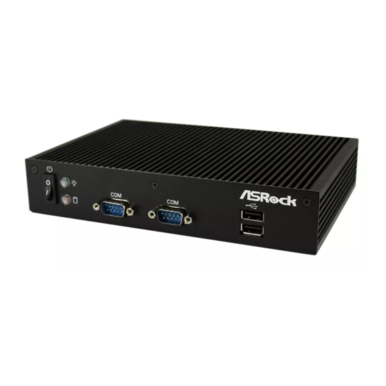
Page 9: Front View
2.2 Front View Description On-/of Switch HDD LED Power LED 2 x COM Ports 2 x USB 2.0 Ports Status LED Deinitions Power LED Status Description Solid Green Power on Power of HDD Status LED Status Description HDD installed... -
Page 10: Rear View
2.3 Rear View No. Description No. Description Antenna Port VGA Port (VGA1) Line out (Lime) HDMI Port (HDMI1) 2 x USB 3.0 Ports (USB01) Antenna Port LAN RJ-45 Port (LAN1)* DC Jack (DC IN) LAN RJ-45 Port (LAN2)* * here are two LEDs on each LAN port. Please refer to the table below for the LAN port LED indications. ACT/LINK LED SPEED LED LAN Port... -
Page 11: Chapter 3 Hardware Installation
Chapter 3 Hardware Installation his chapter provides step-by-step procedures on how to install components. Installation Procedures Removing the chassis bottom cover Installing the memory modules (SO-DIMM) Installing the 2.5-inch hard drive Installing the WiFi module and the WiFi antennas (Optional) -
Page 12: Removing The Chassis Bottom Cover
3.1 Removing the Chassis Bottom Cover 1. Remove the four screws on the bottom case. 2. Lit up and remove the top cover. -
Page 13: Installing Memory Modules (So-Dimm)
3.2 Installing Memory Modules (SO-DIMM) his motherboard provides two 204-pin DDR3 (Double Data Rate 3) SO-DIMM slots. Please install the SO-DIMM module into the DDR3_A2 for the irst priority. It is not allowed to install a DDR or DDR2 memory module into a DDR3 slot; otherwise, this motherboard and SO-DIMM may be damaged. -
Page 14: Installing The 2.5-Inch Hard Drive
3.3 Installing the 2.5-inch Hard Drive 1. Attach the HDD onto the bottom cover with the printed circuit board side facing down. Carefully align the mounting holes in the hard drive and the bottom cover. 2. Secure the hard drive into the place using the four screws. 3. - Page 15 4. Attach the SATA data cable and power cable to the motherboard. SATAII_1 SATA Power Output Connector...
-
Page 16: Installing The Wifi Module And The Wifi Antennas (Optional)
3.4 Installing the WiFi module and the WiFi antennas (Optional) 1. Insert the WiFi Module Card into the mini PCI Express slot (MINI_PCIE1). 2. Tighten the screw that holds the card in place. 3. Attach the SMA Wi-Fi Antenna Cables to the WiFi Module. - Page 17 4. Insert the RP-SMA Wi-Fi Antenna Connectors to the antenna ports on the rear panel. hen fasten the screw nuts to secure the antenna connectors. 5. Connect the two WiFi 2.4/5 GHz Antennas to the antenna connectors. Turn the antenna clockwise until it is securely connected.
-
Page 18: Replacing The Chassis Bottom Cover
3.5 Replacing the Chassis Bottom Cover 1. Replace the top cover. 2. Secure the four screws at the bottom. -
Page 19: Chapter 4 Motherboard
Chapter 4 Motherboard 4.1 Motherboard Layout Industrial DDR3 (Support DDR3L Only) SBC-210 ATX12V1 USB0_1 BIOS Chip USB2_3 CPU_FAN1 USB4_5 LAN1 mini-PCIe / mini-SATA SATAII_2 LAN2 SATAII_1 mini-PCIe USB 3.0 T: USB1 B: USB0 CHA_FAN1 AUDIO Line Out CODEC SPEAKER1... - Page 20 No. Description Panel Power Selection (PNL_PWR1) ATX Power Connector Backlight Power Selection (BKT_PWR1) USB2.0 Headers (USB0_1, USB2_3, USB4_5) mSATA Selection Inverter Power Control Wafer (BLT_PWR1) SATA2 Connectors (SATAII_1, SATAII_2) Backlight & Amp Volume Control (BLT_VOL1) Backlight Control Level (BLT_PWM1) 3-Pin Chassis FAN Connector System Panel Header SATA Power Output Connector Clear CMOS Header...
-
Page 21: Motherboard Speciications
4.2 Motherboard Speciications Form Dimensions 3.5" SBC (5.8-in x 4.0-in) / (146 x 102 mm) Factor ® Intel new Atom Baytrail-M/D/E Series Core Number Processor Max Speed (By CPU) System Cache (By CPU) Chipset BIOS UEFI Mini-PCIe 1 (Half Size) + 1 (Full Size) shared with mSATA... - Page 22 9-36V DC-In using 4-pin ATX PWR Con AT/ATX Supported Power AT: Directly PWR on as power input ready Requirements Power On ATX: Press button to PWR on ater power input ready Environment Temperature 0ºC – 60ºC * For detailed product information, please visit our website: http://www.asrock.com...
-
Page 23: Jumpers Setup
4.3 Jumpers Setup he illustration shows how jumpers are setup. When the jumper cap is placed on the pins, the jumper is “Short”. If no jumper cap is placed on the pins, the jumper is “Open”. he illustration shows a 3-pin jumper whose pin1 and pin2 are “Short”... - Page 24 Panel Power Use this to set up the VDD Selection (LCD_ power of the LVDS connector. VCC) 1-2: +3V (5-pin PNL_PWR1) 2-3: +5V (see p.15, No. 1) 3-4: +5V 4-5: +12V Backlight Power Selection Use this to set up the backlight (LCD_BLT_VCC) power of the LVDS connector.
-
Page 25: Onboard Headers And Connectors
4.4 Onboard Headers and Connectors Onboard headers and connectors are NOT jumpers. Do NOT place jumper caps over these headers and connectors. Placing jumper caps over the headers and connectors will cause permanent damage to the motherboard. SATA2 Connectors... - Page 26 3W Aud io A MP Out put Signal Name Wafer SPK L- (4-pin SPEAKER1) SPK L+ (see p.15 No. 25) SPK R+ SPK R- Chassis Fan Connector Please connect the fan cable to CHA_FAN_SPEED FAN_VOLTAGE (3-pin CHA_FAN1) the fan connector and match the (see p.15 No.
- Page 27 COM Port Headers (10-pin COM1) (see p.15 No. 22) (10-pin COM2) Signal Signal Signal Signal Signal (see p.15 No. 20) Name Name Name Name Name DUMMY CCTS# DDSR# DDTR# RRXD (10-pin COM3) DUMMY RRTS# TTXD DDCD# (see p.15 No. 18) (10-pin COM4) (see p.15 No.
- Page 28 Signal Name Signal Name LVDS_A_ DATA2 LVDS_A_ LVDS_A_ DATA3 DATA3# LVDS_A_CLK# 17 LVDS_A_CLK LVDS_B_ LVDS_B_ DATA0 DATA0# LVDS_B_ DATA1# LVDS_B_ DATA1 LVDS_B_ LVDS_B_ DATA2 DATA2# LVDS_B_ DPLVDD_EN DATA3# LVDS_B_ DATA3 LVDS_B_CLK LVDS_B_CLK# CON_LBKLT_ CON_LBKLT_ LCD_BLT_VCC 37 LCD_BLT_VCC 39 LCD_BLT_VCC Digital Input/Output Pin Signal Signal Header...
- Page 29 Backlight & Amp Volume Signal Name Control GPIO_VOL_UP (7-pin BLT_VOL1) GPIO_VOL_DW (see p.15 No. 8) PWRDN GPIO_BLT_UP GPIO_BLT_DW TPM Header his connector supports Trusted (17-pin TPM1) Platform Module (TPM) system, (see p.15 No. 19) which can securely store keys, digital certiicates, passwords, and data.
-
Page 30: Expansion Slots (Mini-Pcie And Mini-Pcie/Mini-Sata Slots)
4.5 Expansion Slots (mini-PCIe and mini-PCIe/mini-SATA Slots) here is 1 mini-PCIe slot and 1 mini-PCIe/mini-SATA slot on this motherboard. Before installing an expansion card, please make sure that the power supply is switched of or the power cord is unplugged. Please read the documentation of the expansion card and make necessary hardware settings for the card before you start the installation.
Need help?
Do you have a question about the iBOX-210 and is the answer not in the manual?
Questions and answers