Sign In
Upload
Download
Table of Contents
Contents
Add to my manuals
Delete from my manuals
Share
URL of this page:
HTML Link:
Bookmark this page
Add
Manual will be automatically added to "My Manuals"
Print this page
×
Bookmark added
×
Added to my manuals
Manuals
Brands
ASROCK Manuals
Desktop
iBOX 1200 Series
User manual
ASROCK iBOX 1200 Series User Manual
Hide thumbs
1
2
3
4
Table Of Contents
5
6
7
8
9
10
11
12
13
14
15
16
17
18
19
20
21
22
23
24
25
26
27
28
29
30
31
32
33
34
35
36
37
38
39
40
41
42
43
44
45
46
47
48
49
50
51
page
of
51
Go
/
51
Contents
Table of Contents
Bookmarks
Table of Contents
Table of Contents
Chapter 1 Introduction
Package Contents
Product Specifications
Chapter 2 Product Overview
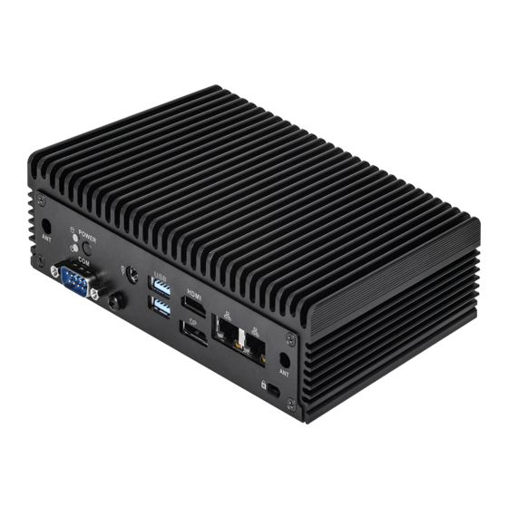
Front View
Rear View
Inside View
Chapter 3 Hardware Installation
How to Remove the Bottom Case
How to Install the Wifi Module
How to Remove the M.2 SSD and the Bracket
How to Install the M.2 SSD
How to Install the 2.5-Inch Hard Drive
How to Install the Memory Modules (DDR4)
How to Install the VESA Bracket
How to Install the Wall Mounting Brackets
How to Install the Din Rail Mounting Bracket (Optional)
Chapter 4 Motherboard
Motherboard Layout
Motherboard Specifications
Onboard Headers and Connectors
Installation of ROM Socket
Expansion Slots (M.2 Slots)
Chapter 5 UEFI Setup Utility
Introduction
UEFI Menu Bar
Navigation Keys
Main Screen
Advanced Screen
CPU Configuration
Chipset Configuration
Storage Configuration
Super IO Configuration
AMT Configuration
ACPI Configuration
USB Configuration
Trusted Computing
Hardware Health Event Monitoring Screen
Security Screen
Boot Screen
Exit Screen
Chapter 6 Software Support
Install Operating System
Advertisement
Quick Links
Download this manual
iBOX 1200 Series
User Manual
Version 1.0
Published June 2022
Table of
Contents
Previous
Page
Next
Page
1
2
3
4
5
Advertisement
Table of Contents
Need help?
Do you have a question about the iBOX 1200 Series and is the answer not in the manual?
Ask a question
Questions and answers
Related Manuals for ASROCK iBOX 1200 Series
Desktop Asrock iBOX-280 User Manual
(31 pages)
Desktop ASROCK iBOX-210 User Manual
(30 pages)
Desktop ASROCK iBOX-220 User Manual
(31 pages)
Desktop ASRock iBOX-220 Quick Installation Manual
(2 pages)
Desktop ASROCK iBOX-315 Quick Installation Manual
(2 pages)
Desktop ASROCK IBOX-WHISKEY LAKE User Manual
(36 pages)
Desktop ASROCK iBOX-420-DL User Manual
(36 pages)
Desktop ASROCK iBOX-345-DL User Manual
(43 pages)
Desktop ASROCK iBOX 1100 Series Quick Start Manual
Mini itx board (2 pages)
Desktop ASROCK iBOX-1265UE User Manual
(51 pages)
Desktop ASROCK iBOX 1300/D4 Series Manual
(2 pages)
Desktop ASROCK iBOX-125U User Manual
(61 pages)
Desktop ASROCK ION 3D SERIES User Manual
(48 pages)
Desktop ASROCK DESKMINI SERIES User Manual
(70 pages)
Desktop ASROCK DeskMini H470 Series Manual
(63 pages)
Desktop ASROCK Beebox Series Manual
(54 pages)
This manual is also suitable for:
Ibox-1265ue
Ibox-1245ue
Ibox-1215ue
Table of Contents
Print
Rename the bookmark
Delete bookmark?
Delete from my manuals?
Login
Sign In
OR
Sign in with Facebook
Sign in with Google
Upload manual
Upload from disk
Upload from URL


Need help?
Do you have a question about the iBOX 1200 Series and is the answer not in the manual?
Questions and answers