Table of Contents
Advertisement
Quick Links
Download this manual
See also:
User Manual
Advertisement
Table of Contents

Subscribe to Our Youtube Channel
Related Manuals for Colormetrics P1000

Summary of Contents for Colormetrics P1000
-
Page 1: Installation Guide
P1000 Installation Guide P1000 Installation Guide Ver. Draft 1.2_2009/06/29... - Page 2 P1000 Installation Guide System box module installation caution note CAUTION: Before installing or removing the CPU Box into the system unit, please make sure that the system power is turned off and the AC power adaptor is disconnected from the system unit.
- Page 3 P1000 Installation Guide ③. Attach the Magnetic front base cover into system unit. ④. Connect the AC power adaptor to the system as shown. ⑤.Turn on the power.
-
Page 4: Declaration Of Conformity
P1000 Installation Guide Federal Communications Commission (FCC) This equipment has been tested and found to comply with the limits for a Class A digital device, pursuant to Part 15 of the FCC Rules. These limits are designed to provide reasonable protection against harmful interference in a residential installation. -
Page 5: Important Safety Information
P1000 Installation Guide Important Safety Information SAFETY INSTRUCTIONS 1. Please read these safety instructions carefully. 2. Keep this User’s Manual for later reference. 3. Disconnect this equipment from the AC outlet before cleaning. Don’t use liquid or spray detergent for cleaning. - Page 6 P1000 Installation Guide Copyright The information in this guide is subject to change without prior notice. The manufacturer shall not be liable for technical or editorial errors or omissions contained herein, nor for incidental or consequential damages resulting from the furnishing, performance, or use of this material.
-
Page 7: Table Of Contents
Installing MSR/Fingerprint/I-Button module ................ 28 Installing 8.9” pole display and VFD pole display............... 29 P1000 and 8.9” 15cm pole display full view..............31 P1000 and VFD 15cm pole display full view ..............31 Installing Cash Drawer ......................32 Main Board Configuration....................33 Main Board Pin Definition ..................... - Page 8 P1000 Installation Guide Chapter 3 Software Setup ....................... 48 Driver Software List......................48 Intel Chipset Driver Installation..................49 Intel Graphics Driver Installation ..................50 ELO Touch Screen Driver Installation ................51 Audio Driver Installation ..................... 53 Gigabit LAN Driver Installation................... 54 Wireless LAN Driver Installation (optional) ...............
-
Page 9: Chapter 1 Introduction
The solid Magnesium-Aluminum & Aluminum Die-casting Housing design enhances heat dissipation and passes EMI testing. P1000 can easily replace the front panel cover, providing a variety of colors for you to choose from for a variety of business occasions and indoor space. -
Page 10: How To Use This Manual
How to Use This Manual This manual contains all the information you need to set up and use P1000. In addition, you can also consult the manuals for the operating system and added hardware. Chapter 1 Provides an introduction what you have in the box and give you an overview of the product specification, appearance and interface. -
Page 11: Specifications
Specifications System Configuration Intel Pentium M / Celeron M Processor, supports 400/533 MHz FSB CPU(μPGA) level depend on CPU Cash Memory Intel 915 GME+ICH6 System Chipset Default 256MB, maximum up to 2 GB System Memory Support Compact Flash Card Compact Flash Internal 2.5”... -
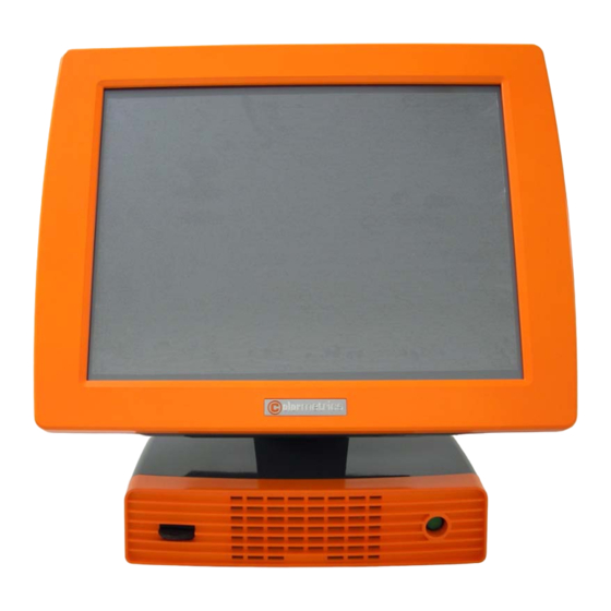
Page 12: A Visual Tour Of P1000
0 ℃ ~ 35 ℃ Operating temperature (*CPU needs Cooler & silicone heatsink paste*) CE, RoHS EMI/Safety A Visual Tour of P1000 Before you start, take a few moments to become familiar with P1000. Front View MSR/Fingerprint/ LCD Display I-Button Assembly USB Port Cover... -
Page 13: Rear View
Rear View WiFi/Bluetoooth Cover Display Hinge Display Cover RFID/HDD Cover IO Cover... - Page 14 Packaging Content The following items are standard with P1000: AC power cord Power adaptor COM6 Adaptor Cable Utility and Motherboard chipset driver POS Body CPU Box module Front panel Cover module Front base Cover module...
- Page 15 The following items are optional: 2-in-1 ( Magnetic Stripe Card Reader + Fingerprint Reader ) 2-in-1 (Magnetic Stripe Card Reader + I-Button Reader ) 2-way choice ( WiFi or Bluetooth ) Radio Frequency Identification (RFID) Uninterruptible power supply (UPS) 15cm pole VFD customer display 15cm pole 8.9”...
-
Page 16: Dimensions
Dimensions P1000 Dimensions P1000 and MSR Dimensions... -
Page 17: P1000 And 15Cm 8.9" Pole Display Dimensions
P1000 and 15cm 8.9” Pole Display Dimensions... -
Page 18: P1000 And 15Cm Vfd Pole Display Dimensions
P1000 and 15cm VFD Pole Display Dimensions... -
Page 19: Connector Panels
2 PIN Socket DC Power Connector POWER Connects P1000 to the power supply. It is a Giga LAN port which is used to hook P1000 LAN RJ-45 Connector to a local area network. The serial port COM6 can be used to connect... -
Page 20: Second Connector Panel
Second Connector Panel The second connector panel is located on the front side of the base. ITEM I/O Port Connector Type Description The USB (Universal Serial Bus) port can be used USB TYPE A to connect USB devices. ATX Power Switch function. Power Button POWER SWITCH The LED standers power on or power off. -
Page 21: Chapter 2 Hardware Setup
Chapter 2 Hardware Setup P1000 Assembly Warnings and Cautions Before performing hardware upgrades be sure to carefully read all of the applicable instructions, cautions, and warnings in this guide. WARNING! To reduce the risk of personal injury from electrical shock, hot surfaces, or fire: Disconnect the power cord from the wall outlet and allow the internal system components to cool before touching. -
Page 22: Installing Cpu Box
Installing CPU box Remove all removable media, such as compact discs, from the system unit. Turn off the system power properly through the operating system, then turn off any external devices. Disconnect the power cord from the power outlet and disconnect any external devices. CAUTION: To prevent loss of work and damage to the system or drive: If you are inserting or removing a drive, shut down the operating system properly, turn off the system, and... - Page 23 Attach the Magnetic front base cover into system unit. Connect the power cord and any external devices, then turn on the system.
-
Page 24: Changing Front Panel Cover
Changing Front Panel Cover Remove all removable media, such as compact discs, from the system unit. Turn off the system power properly through the operating system, then turn off any external devices. Disconnect the power cord from the power outlet and disconnect any external devices. CAUTION: Regardless of the power-on state, voltage is always present on the main board as long as the system is plugged into an active AC outlet. - Page 25 Attach the Magnetic front panel cover into system unit. Press the front panel cover into place completely. Replace 4 screws that secure the front panel cover to the system unit.
-
Page 26: Changing Front Base Cover
Changing Front Base Cover Remove all removable media, such as compact discs, from the system unit. Turn off the system power properly through the operating system, then turn off any external devices. Disconnect the power cord from the power outlet and disconnect any external devices. CAUTION: Regardless of the power-on state, voltage is always present on the main board as long as the system is plugged into an active AC outlet. -
Page 27: Removing The Cpu Box And Box Cover
Removing the CPU box and box cover Remove all removable media, such as compact discs, from the system unit. Turn off the system power properly through the operating system, then turn off any external devices. Disconnect the power cord from the power outlet and disconnect any external devices. CAUTION: To prevent loss of work and damage to the system or drive: If you are inserting or removing a drive, shut down the operating system properly, turn off the system, and... -
Page 28: Replacing The Cpu Box Cover
Slide the CPU box cover then lift it off the box unit . Replacing the CPU box cover Place the CPU box cover on the chassis in front of the final position and slide it back into place until it stops. Replace the 2 screws that secure the CPU box cover to the chassis. -
Page 29: Installing Ups
Installing UPS Remove all removable media, such as compact discs, from the system unit. Turn off the system power properly through the operating system, then turn off any external devices. Disconnect the power cord from the power outlet and disconnect any external devices. CAUTION: To prevent loss of work and damage to the system or drive: If you are inserting or removing a drive, shut down the operating system properly, turn off the system, and... - Page 30 NOTE: Before connecting the battery connector cable to main board, please refer to page 32 External BAT connector pin description. Secure battery box cover with 2 screws. Replace CPU box cover and CPU box. Replace the front base cover. Reconnect the power cord and any external devices, then turn on the system.
-
Page 31: Installing Additional Memory Card
Installing Additional Memory Card The memory sockets on the main board can be populated with up to two industry-standard DIMMs. These memory sockets are populated with at least one preinstalled DIMM. To achieve the maximum memory support, you can populate the main board with up to 2-GB of memory. Populating DIMM Sockets There are two DIMM sockets on the main board. - Page 32 Remove all removable media, such as compact discs, from the system unit. Turn off the system power properly through the operating system, then turn off any external devices. Disconnect the power cord from the power outlet and disconnect any external devices. CAUTION: Regardless of the power-on state, voltage is always present on the main board as long as the system is plugged into an active AC outlet.
-
Page 33: Removing And Replacing The Sata Hard Disk
Removing and Replacing the SATA Hard Disk NOTE: The system does not support Parallel ATA (PATA) hard drives. Before you remove the old hard drive, be sure to back up the data from the old hard drive so that you can transfer the data to the new hard drive. - Page 34 Replace new Hard Disk to the HDD tray holder, and secure the screw. Insert the HDD box into the socket, ensuring that the HDD box is fully inserted and properly seated. Replace 2 screws that secure the HDD tray holder. Replace the HDD cover and 2 screws.
-
Page 35: Installing Compact Flash Card
CF card and 2.5” HDD master/slave setting: P1000 allow the use of CF card and hard disk at the same time, but user need to set the system BIOS to boot the order. When P1000 installed only the CF card, or just install 2.5 "hard disk, BIOS will be... -
Page 36: Installing Msr/Fingerprint/I-Button Module
Installing MSR/Fingerprint/I-Button module An optional 2-in-1(Magnetic Stripe Reader + Fingerprint Reader) or 2-in-1(Magnetic Stripe Reader + I-Button Reader) can be installed on the right side of P1000. Remove all removable media, such as compact discs, from the system unit. Turn off the system power properly through the operating system, then turn off any external devices. -
Page 37: Installing 8.9" Pole Display And Vfd Pole Display
Installing 8.9” pole display and VFD pole display Remove all removable media, such as compact discs, from the system unit. Turn off the system power properly through the operating system, then turn off any external devices. Disconnect the power cord from the power outlet and disconnect any external devices. CAUTION: Regardless of the power-on state, voltage is always present on the main board as long as the system is plugged into an active AC outlet. - Page 38 Replace the I/O Cover and thumb screws. Reconnect the power cord and any external devices, then turn on VFD/LCD power, Finally, turn on the system power.
-
Page 39: P1000 And 8.9" 15Cm Pole Display Full View
P1000 and 8.9” 15cm pole display full view P1000 and VFD 15cm pole display full view... -
Page 40: Installing Cash Drawer
Before connecting the cash drawer to P1000, please make sure the driver voltage and cable pin assignment of the cash drawer matches the definition of the cash drawer port of P1000. Please refer to page 36 Cash Drawer Power Select Connector. -
Page 41: Main Board Configuration
Main Board Configuration Main Board Pin Definition CN10 CN15 CN13 CN14 Clear CMOS connector 1 2 3 CN1 Jumper Function Default Clear CMOS... - Page 42 3 2 1 External BAT connector CN14 PIN No. Description BAT+ BAT_T+ CN10 CPU Fan connector PIN No. Description FAN_IO1 CN10 CN15 FAN1_12V FAN_PWM1 3 2 1 3 2 1 CN15 System Fan connector PIN No. Description FAN_IO2 FAN2_12V FAN_PWM2 CN13 Power Button connector PIN No.
-
Page 43: Clearing Cmos
Clearing CMOS Remove all removable media, such as compact discs, from the system unit. Turn off the system power properly through the operating system, then turn off any external devices. Disconnect the power cord from the power outlet and disconnect any external devices. CAUTION: Regardless of the power-on state, voltage is always present on the main board as long as the system is plugged into an active AC outlet. -
Page 44: I/O Board Configuration
I/O Board Configuration The IOTR board transform signals form main board to TOP IO board and Bottom IO board. IOTR Board Pin Definition Top side faces the PC box Locate the Power I/O Jumpers inside the System case. MD_1 MD_2 IO_BUS1 IO_BUS2 Cash Drawer Power Select Connector... - Page 45 COM1 & COM2 Power Select Connector PIN No. Description PIN No. Description RI_A RI_B COM5 & COM6 Power Select Connector PIN No. Description PIN No. Description RI_E RI_F Select COM Port Power as shown in the table COM Port Connect Description Connector COM1...
- Page 46 Display I/O Connector MD_1 PIN No. Description PIN No. Description SPK_R+ SPK_R- PVDD PVDD RXO0- RXO0+ RXO1- RXO1+ RXO2- RXO2+ RXOCLK- RXOCLK+ RXO3- RXO3+ ON/OFF LCD_ADJ UD5- UD5+ UD6- UD6+ KB-CK KB-DA MD_2 Display I/O Connector PIN No. Description PIN No. Description SPK_L+ SPK_L-...
- Page 47 CTS_C DSR_C DTR_C IO_BUS2 IO_BUS1 I/O BUS1(164 PIN) & IO BUS2 (64 PIN) PCI Express Connector connect to the main board GF1 & GF2. Bottom side faces the I/O Connector 2ND_DISPLAY Second Display 36 PIN PCI Express Connector PIN No. Description PIN No.
- Page 48 DDCCLK VSYNC DDCDAT HSYNC BLUE TOP_BUS TOP_BUS 98 PIN PCI Express Connector connects to the TOP IO board TOP_BUS Golden Finger. PIN No. Description PIN No. Description VSYNC DTR_D HSYNC DSR_D DDCCLK CTS_D DDCDAT RTS_D BLUE RX_D TX_D LINE_HP LINEO_L LINEO_R LAN_L2- LAN_L2+...
- Page 49 LAN2+ UD2+ LAN1- UD2- LAN1+ LAN0- UD1+ LAN0+ UD1- GND_LAN OUT1 IN_0 OUT0 Drawer Power Select Drawer Power Select BTM_BUS BTM_BUS 98 PIN PCI Express Connector connects to the BOTTOM IO board BTM_BUS Golden Finger. PIN No. Description PIN No. Description GND_FIELD DC_IN...
- Page 50 RTS_E DTR_E RX_E DSR_E TX_E CTS_E DCD_E PSLCT PBUSY PACKX PSLINX PINITX PERX PAFDX PSTBX DTR_B CTS_B TX_B RTS_B RX_B DSR_B DCD_B RTS_A DTR_A RX_A DSR_A TX_A CTS_A DCD_A...
-
Page 51: Top Io Board Pin Definition
Top IO Board Pin Definition TOP IO board covers the I/O ports to the IOTR board. Including: audio port, LAN, Cash Drawer, 5V power USB,12V power USB,USB. LINE_OUT Audio line output EAR Connector PIN No. Description GND_SP LO_R LO_L LO_HP RJ-45 LAN Port PIN No. - Page 52 P_USB1 Power USB Port PIN No. Description PIN No. Description UD1- UD1+ USB_B1 USB Port PIN No. Description PIN No. Description UD3- UD3+ UD4- UD4+ DRAW RJ-11 Cash drawer Port PIN No. Description PIN No. Description DGO_0 IN_0 V_DRAW DGO_1...
-
Page 53: Bottom Io Board Pin Definition
Bottom IO Board Pin Definition BOTTOM IO board covers the I/O ports to the IOTR board. Including: DC IN, RJ-45 COM6, COM1, COM2, COM5, LPT1. COM6&VFD select Connector PIN No. Description PIN No. Description RTS_F CTS_F RTSF CTSF RI_F COM6 COM6 uses the RJ-45 connector to accept VFD customer display. - Page 54 Mode2 RJ-45 connector used for VFD device J1(Bottom IO board) J3( IOTR board) 11-12 Short (+12V) Short Short RJ-45 Pin definitions PIN No. Description PIN No. Description +12V +12V DTRF DSRF DC_IN1 DC Power Jack connector PIN No. Description DC_IN DC_IN COM1&COM2&COM5 RS232 port COM1,COM2 and COM5 D-SUB connector...
- Page 55 LPT1 Parallel port LPT1 SCSI connector PIN No. Description PIN No. Description STBX ACKX BUSY SLCT AFDX INITX SLINX GND_LPT GND_LPT GND_LPT GND_LPT GND_LPT GND_LPT GND_LPT GND_LPT...
-
Page 56: Chapter 3 Software Setup
Chapter 3 Software Setup Driver Software List Driver Driver Setup Location Intel Chipset <CD>:\Driver\Intel INF\PWI-M91x Intel Graphics <CD>:\Driver\VGA\PWI-M91x ELO Touch Screen <CD>:\Driver\Touch\Elo Abon Touch Screen <CD>:\Driver\Touch\Abon RealTek Audio <CD>:\Driver\Audio\RealTek AC97 PCIe GigaBit LAN <CD>:\Driver\LAN\PCIe_GLAN 802.11b/g Wireless <CD>:\Driver\WLAN\802.11bg USB RFID <CD>:\Driver\RFID\USB driver Fingerprint Reader <CD>:\Driver\FingerPrint\UareU\DP Plat frsw 3.2 Cash Drawer and UPS... -
Page 57: Intel Chipset Driver Installation
Intel Chipset Driver Installation 1.Locate and Run the Setup.exe file on the 2.Click the Next button on the Welcome CD in folder <CD>:\Intel INF\PWI-M91x Screen. 3.Click Yes on the License Agreement 4.Click Next on the Information Screen. Screen. ----- 5.When Installation is complete, click ----- Finish. -
Page 58: Intel Graphics Driver Installation
Intel Graphics Driver Installation 1.Locate and Run the win2k_xp1425.exe file on the CD in folder <CD>:\VGA 2.Click Next on the Startup Screen. Driver\PWI-M91x 3.Click the Next button on the Welcome 4.Click Yes on the License Agreement Screen. Screen. 5.Click Next on the Setup Progress Screen. 6.When Installation is complete, click Finish. -
Page 59: Elo Touch Screen Driver Installation
ELO Touch Screen Driver Installation 1.Locate and Run the sw600188.exe file on 2.Click Unzip on the WinZip Self-Extractor the CD in folder <CD>:\Touch Driver\Elo Window. 3.Select Default Installation Language then 4.Select Install Serial Touchscreen Drivers and click Next. then click Next. 5.Click Yes on the License Agreement 6.Select Auto-Detect Elo Device then click Screen. - Page 60 7.Select COM3 then click Next. 8.Click Next. 10.After the computer has restarted, click 9.When Installation is complete, click Align on the Elo Touchscreen Properties Finish and Restart the System. Screen. ----- 11.Calibrate the three red points as ----- instructed.
-
Page 61: Audio Driver Installation
Audio Driver Installation 1.Locate and Run the WDM_A381.exe file on the CD in folder <CD>:\Audio 2.Click Next on the Welcome Screen. Driver\RealTek AC97 3.Click Continue Anyway on Hardware 4.When Installation is complete, click Finish. Installation Screen. -
Page 62: Gigabit Lan Driver Installation
Gigabit LAN Driver Installation 1.Locate and Run the Setup.exe file on the 2.Select Modify then click Next. CD in folder <CD>:\LAN Driver\PCIe_GLAN 4.Click Continue Anyway on Hardware 3.Select DefaultFeature and click Next. Installation Screen. ----- 5.When Installation is complete, click ----- Finish. -
Page 63: Wireless Lan Driver Installation (Optional)
Wireless LAN Driver Installation (optional) 1.First, plug in USB WLAN Interface Module. 2.Locate and Run the Setup.exe file on the CD 3.Click Next on the License Agreement Screen. in folder <CD>:\ Driver\WLAN\ 802.11bg 4.Select Ralink Configuration Tool then 5.Select Optimize WiFi mode then click Next. click Next. -
Page 64: Rfid Driver Installation (Optional)
RFID Driver Installation (optional) 1.Plug in USB RFID Module and wait for the following screen. 2.Select Yes, this time only and then click 3.Select Install from a list specific location then click Next Next. 5.Click Finish to complete USB Serial 4.Click Next Converter Installation -----... -
Page 65: Fingerprint Reader Driver Installation (Optional)
Fingerprint Reader Driver Installation (optional) 1.Plug in 2 in 1 Fingerprint Reader and MSR module. 2.Locate and Run the Setup.exe file in folder <CD>:\ 3.Click Next on the Welcome Screen. Driver\FingerPrint\UareU\DP Plat frsw 3.2 4.Click Next on the License Agreement 5.Click Next. -
Page 66: System Driver Installation (Required For Cash Drawer And Ups)
System Driver Installation (Required for Cash Drawer and UPS) 1. Locate and Run the Setup.exe file in 2. Click Next on the Welcome Screen. folder <CD>:\Driver\System 4. Click Finish on the Installation Complete 3. Click Install on the Ready to Install Screen. -
Page 67: Opos Driver Installation
OPOS Driver Installation 1. Locate and Run the Setup.exe file in 2. Click Next on the Welcome Screen. folder <CD>:\Driver\OPOS 3. Click Install on the Ready to Install 4. Wait while the driver is installed. screen. ----- 5. Click Finish on the Installation Complete Screen. -
Page 68: Msr Driver Installation (Optional)
MSR Driver Installation (optional) First, plug-in 2 in 1 Fingerprint Reader and MSR module. Reboot system to complete installation. -
Page 69: Appendix A. Sample C++ Cash Drawer Code For Windows
Appendix A. Sample C++ Cash Drawer Code for Windows NOTE: Requires installation of System Driver (see page 58). 1.Open Cash Drawer // IOCTL Codes #define GPD_TYPE 56053 #define ADV_OPEN_CTL_CODE CTL_CODE(GPD_TYPE, 0x920, METHOD_BUFFERED, FILE_ANY_ACCESS) #define ADV_STATUS_CTL_CODE CTL_CODE(GPD_TYPE, 0x900, METHOD_BUFFERED, FILE_ANY_ACCESS) void OpenDrawer(UCHAR uWhichDrawer) // uWhichDrawer = 1 => CD#1, uWhichDrawer = 2 => CD#2 HANDLE hFile;... -
Page 70: Appendix B. Sample Visual Basic Cash Drawer Code For Windows
Appendix B. Sample Visual Basic Cash Drawer Code for Windows NOTE: Requires installation of System Driver (see page 58).
Need help?
Do you have a question about the P1000 and is the answer not in the manual?
Questions and answers