Table of Contents
Advertisement
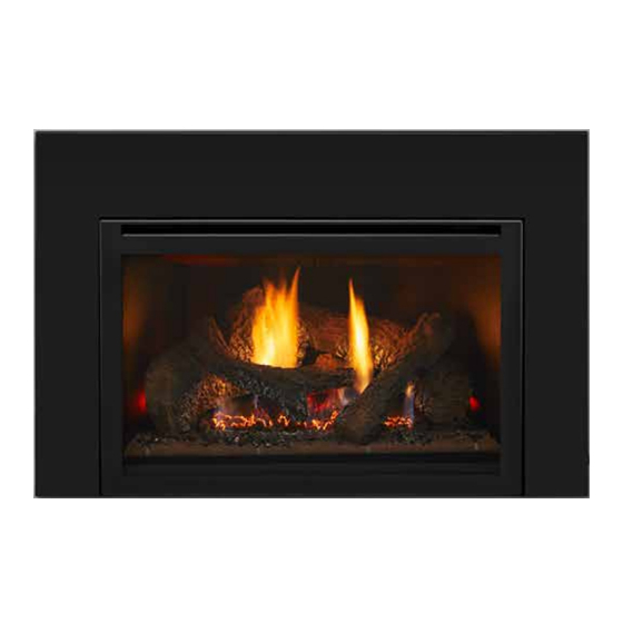
INSTALLATION AND OPERATION INSTRUCTIONS
High temperatures may ignite clothing or other fl ammable materials.
• Keep clothing, furniture, draperies and other fl ammable materials away.
This appliance has been supplied with an integral barrier to prevent direct contact with the
fi xed glass panel. DO NOT operate the appliance with the barrier removed.
THIS MANUAL MUST BE USED FOR INSTALLATION AND RETAINED
HEAT & GLO, a brand of Hearth & Home Technologies Inc.
7571 215
This product may be covered by one or more of the following patents: (United States) 4593510, 4686807, 4766876, 4793322, 4811534, 5000162, 5016609, 5076254, 5113843,
5191877, 5218953, 5263471, 5328356, 5341794, 5347983, 5429495, 5452708, 5542407, 5601073, 5613487, 5647340, 5688568, 5762062, 5775408, 5890485, 5931661, 5941237,
5947112, 5996575, 6006743, 6019099, 6048195, 6053165, 6145502, 6170481, 6237588, 6296474, 6374822, 6413079, 6439226, 6484712, 6543698, 6550687, 6601579, 6672860,
6688302B2, 6715724B2, 6729551, 6736133, 6748940, 6748942, 6769426, 6774802, 6796302, 6840261, 6848441, 6863064, 6866205, 6869278, 6875012, 6880275, 6908039,
6919884, D320652, D445174, D462436; (Canada) 1297749, 2195264, 2225408, 2313972; (Australia) 780250, 780403, 1418504 or other U.S. and foreign patents pending.
MODEL: ATS-AU-D
AUSTRALIAN GAS ASSOCIATION APPROVED
AGA Approval Number 5543
WARNING
HOT SURFACES!
Glass and other surfaces are hot during operation AND cool down.
Hot glass will cause burns.
• DO NOT touch glass until it is cooled
• NEVER allow children to touch glass
• Keep children away
• CAREFULLY SUPERVISE children in same room as fi replace.
• Alert children and adults to hazards of high temperatures.
BY HOMEOWNER FOR OPERATION AND MAINTENANCE.
Street West, Lakeville, MN 55044, USA, www.heatnglo.com
th
Heat & Glo • ATS-AU-D • 327-900 Rev. F • 6/09
1
Advertisement
Table of Contents

Subscribe to Our Youtube Channel
Related Manuals for Heat & Glo ATS-AU-D


Summary of Contents for Heat & Glo ATS-AU-D
- Page 1 6688302B2, 6715724B2, 6729551, 6736133, 6748940, 6748942, 6769426, 6774802, 6796302, 6840261, 6848441, 6863064, 6866205, 6869278, 6875012, 6880275, 6908039, 6919884, D320652, D445174, D462436; (Canada) 1297749, 2195264, 2225408, 2313972; (Australia) 780250, 780403, 1418504 or other U.S. and foreign patents pending. Heat & Glo • ATS-AU-D • 327-900 Rev. F • 6/09...
- Page 2 fi re hazard and will void the warranty. Heat & Glo, a brand of Hearth & Home Technologies, Inc. 7571 215 Street West, Lakeville, MN 55044 Copyright 2009 • Printed in U.S.A. Heat & Glo • ATS-AU-D • 327-900 Rev. F • 6/09...
-
Page 3: Table Of Contents
3.3 Parts Replacement .................. 19 3.4 Adjustments and Replacement Parts ............19 3.5 Troubleshooting ..................20 4.0 Replacement Parts ..................22 Limited Lifetime Warranty ................25 = Contains updated information. Heat & Glo • ATS-AU-D • 327-900 Rev. F • 6/09... - Page 4 ASSEMBLY LOWER GRILLE GAS LINE ACCESS CONTROL EXHAUST FLUE VALVE COLLAR DATA BADGE & LABELS INLET FLUE COLLAR ON/OFF SWITCH ELECTRICAL LOW VOLTAGE JUNCTION BOX WIRES ACCESS FIGURE 1 Heat & Glo • ATS-AU-D • 327-900 Rev. F • 6/09...
-
Page 5: Minimum Fireplace Opening
NOTE: If exhaust collar on insert and fi replace damper do not line up, add 4 inches (102 mm) to minimum fi replace opening height to accommodate 816 mm bends in vent pipe. FIGURE 2 Heat & Glo • ATS-AU-D • 327-900 Rev. F • 6/09... - Page 6 THE INLET AIR PIPE MUST ONLY BE CONNECTED TO THE INLET AIR COL- LAR OF THE UNIT AND ATTACHED TO THE INLET AIR COLLAR OF THE TERMINATION CAP. INLET AIR FLUE PIPE FIGURE 3 Heat & Glo • ATS-AU-D • 327-900 Rev. F • 6/09...
- Page 7 TERMINATION CAP INLET AIR EXHAUST COLLAR COLLAR INLET AIR STARTING COLLAR EXHAUST STARTING COLLAR FIGURE 4 Heat & Glo • ATS-AU-D • 327-900 Rev. F • 6/09...
-
Page 8: Installation Instructions
3.3 inch (84 mm) fl exible fl ue pipe for the exhaust, Kit Instructions to ensure that a proper fl ue installation one (1) LINK-DV30B Vertical Termination Kit. is completed. Consult your local Building Codes before beginning the installation. Heat & Glo • ATS-AU-D • 327-900 Rev. F • 6/09... -
Page 9: Connecting The Flue Pipe
FLAME. NOTE: THE GAS SUPPLY LINE SHOULD BE PURGED OF ANY TRAPPED AIR PRIOR TO THE FIRST FIRING OF THE UNIT. GAS LINE ACCESS GAS CONTROL VALVE FIGURE 6 Heat & Glo • ATS-AU-D • 327-900 Rev. F • 6/09... -
Page 10: Fan
AIR LEAKS. of the surround and push the back of the switch through the hole - it will be retained in the hole. Heat & Glo • ATS-AU-D • 327-900 Rev. F • 6/09... -
Page 11: Log Placement
Place log #1 in the back of the heater, locating it's slot on the right over the protruding tab. The left end of the log is positioned by the two bend up tabs shown in Photo A. Heat & Glo • ATS-AU-D • 327-900 Rev. F • 6/09... - Page 12 #3 fi ts over the bar grate. LOG #4 (SRV327-704): Place the bottom left corner of log #4 behind log #2 and rest its top right corner on log #1. Heat & Glo • ATS-AU-D • 327-900 Rev. F • 6/09...
- Page 13 Rest log #5 in the cutouts on both log #1 and log #2 as shown. LOG #6 (SRV438-724): Position the "Y" end of log #6 into the cutout on log #4 and its opposite end into the groove on log #2. Heat & Glo • ATS-AU-D • 327-900 Rev. F • 6/09...
-
Page 14: Finishing
3/8 in. (10 mm) TOP OF UNIT FIGURE 9 FIGURE 8 Proper gas log positioning is shown on pages 11-13. Follow Section 3.5 TROUBLESHOOTING for adjusting the appliance to operate properly. Heat & Glo • ATS-AU-D • 327-900 Rev. F • 6/09... -
Page 15: Operating Instructions
Access to produce and does not affect the operation or longevity of this compartment is gained by rotating the grille up. See the heater. Figure 1. Heat & Glo • ATS-AU-D • 327-900 Rev. F • 6/09... -
Page 16: Safety And Lighting Information
• Do not touch any electric switch; do not use any phone in your building. • Immediately call your gas supplier from a neighbor’s phone. Follow the gas supplier’s instructions. Heat & Glo • ATS-AU-D • 327-900 Rev. F • 6/09... -
Page 17: Lighting Instructions
3. Turn the valve control knob clockwise to the "Pilot" position, then depress knob and continue 2. Open the bottom grille. turning to "OFF" position. 4. Close the bottom grille. Heat & Glo • ATS-AU-D • 327-900 Rev. F • 6/09... -
Page 18: Fan Operation
B. IMPORTANT: TURN OFF GAS BEFORE SERVIC- ING APPLIANCE. IT IS RECOMMENDED THAT A COMPETENT SERVICE TECHNICIAN PERFORM SERVICE CHECK-UPS AT THE BEGINNING OF EACH HEATING SEASON. Heat & Glo • ATS-AU-D • 327-900 Rev. F • 6/09... -
Page 19: Removal Of Covers For Servicing
• Unscrew the brackets at both ends of the burner and slide the burner to the right away from the burner orifi ce. 2. Pilot Assembly/Ignition System Heat & Glo • ATS-AU-D • 327-900 Rev. F • 6/09... -
Page 20: Troubleshooting
Clean and adjust pilot fl ame for maximum fl ame impingement on the or too low, or blowing (high), lem. thermocouple. Follow lighting instruction carefully. causing pilot safety to drop out. Heat & Glo • ATS-AU-D • 327-900 Rev. F • 6/09... - Page 21 Insuffi cient oxygen being burner. supplied Check to make sure that no material has been placed at the burner base. Be sure glass is tightened properly on unit, particularly on top corners. Heat & Glo • ATS-AU-D • 327-900 Rev. F • 6/09...
-
Page 22: Replacement Parts
Limited Lifetime Warranty Heat & Glo • ATS-AU-D • 327-900 Rev. F • 6/09... - Page 23 Heat & Glo • ATS-AU-D • 327-900 Rev. F • 6/09...
- Page 24 Melbourne Jetmaster 444 Swan Street Richmond 3121 (03) 9429-5573 Perth Fireplace Corner 277 Lord Street East Perth 6000 (08) 9228-2600 Sydney Jetmaster 10 Martin Avenue Arncliff 2205 (02) 9597-7222 Heat & Glo • ATS-AU-D • 327-900 Rev. F • 6/09...
Need help?
Do you have a question about the ATS-AU-D and is the answer not in the manual?
Questions and answers