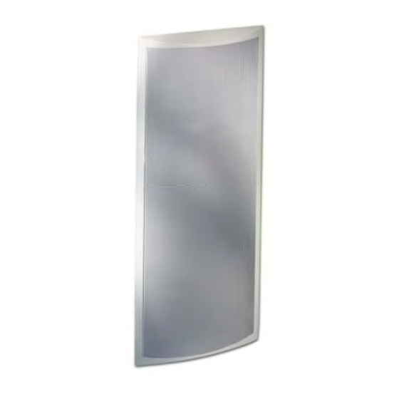
Summary of Contents for Artison RCC300-SM
- Page 1 INSTALLATION GUIDE RCC300-SM Subwoofer Module RCC300-FS Freestanding Subwoofer RCC300-SA Subwoofer Amplifier RCC300-CM Cabinet Mount...
- Page 3 INTRODUCTION The following information will guide you through the installation and setup of your Artison RCC 300 Subwoofer Module, RCC 300 Freestanding Subwoofer, RCC 300 Subwoofer Amplifier and RCC 300 Cabinet Mount.
- Page 4 Paint can damage the components which would VOID your Warranty. The minimum mounting depth for the RCC300-SM is 3¾” (95.5 mm), i.e. a 2x4 stud is 3½” deep add ¼”, ½” or ⅝” thick drywall and the RCC300-SM will fit. The maximum drywall thickness the RCC300-SM can be mounted in is 1.3125”...
- Page 5 5. Carefully tighten the four dog leg clamps on the RCC300-SM using a #2 Philips Head Screwdriver. 6. The grille for the RCC300-SM is held in place by magnets. Simply position the grille on the front of the module into the recessed area.
-
Page 6: Subwoofer Setup
RCC 300 FREESTANDING SUBWOOFER (RCC300-FS) SUBWOOFER PLACEMENT AND ORIENTATION The RCC 300 Freestanding Subwoofer comes with four rubber feet to attach to the side of your choice. Carefully decide what placement and orientation are best for the subwoofer, supplied rubber feet are not removable once applied. The classical rule for subwoofer placement is that the subwoofer should be placed near the same wall the front channels are located, at one-third of the total distance of the wall. - Page 8 HEX Codes are available on the Artison Web site. The Front Panel of the RCC300-SA has an IR Receiver and there is a second hard wired feed thru jack that can be connected to an integrated control system on the rear panel.
- Page 9 RCC300-SA FRONT PANEL CONTROLS GAIN – The position of this knob controls the overall gain (volume) of the subwoofer. Press this button in and it will spring out into a rotating knob, press it back in to hide it. The front panel gain control will become the master gain control until the remote is used.
-
Page 10: Audio Outputs
2. The Red Switch is the input voltage setting; select the appropriate 120V or 230V setting. 3. Connect the detachable IEC Power Cord underneath the Red Voltage Selection Switch. AUDIO OUTPUTS 1. Connect the speaker wires to the Binding Posts. NOTE: Red is Positive and Black is Negative. -
Page 11: Power Modes
IR FEEDTHRU 1. Connect a ⅛” Stereo MINIJACK to control the RCC600-SA via your integrated control system. 2. Both the IR Feedthru Jack and the Front Panel IR receiver are designed to allow the User functions to be programmed into an external remote. The Hexadecimal codes for the amplifier are located on the web at: http://www.artisonusa.com POWER MODES... - Page 12 RCC300-SA comes from the factory with the 80Hz setting that is recommended for use with the Artison LCR speakers. If used in conjunction with any other speakers consult with the manufacturer for the correct setting for the integration of the subwoofer with the satellites.
- Page 13 Eigen-modes and provides a more uniform response to a wider listening area. Each RCC300-SA has the capability for running two RCC300-SM, or two RCC300-FS. 1. AUTO EQ MIC – This is the input jack for the ARMC Microphone.
-
Page 14: Installation
One Long, Three Short Flashes – Over Temperature Indicator. Be sure that the amplifier has adequate ventilation. If the situation continues to exist contact Artison. Calibrate Button – Place the supplied microphone in the desired listening position and plug it into the AUTO EQ MIC input jack. -
Page 15: Limited Warranty
Department), 774 Mays Blvd., Suite 10-183, Incline Village, NV 89451. We will promptly advise you of what action to take. We may direct you to an authorized Artison Service Center or ask you to send your speaker to the factory for repair. You will need to present the original bill of sale to establish the date of purchase.


Need help?
Do you have a question about the RCC300-SM and is the answer not in the manual?
Questions and answers