Advertisement
Quick Links
Quick Start Guide
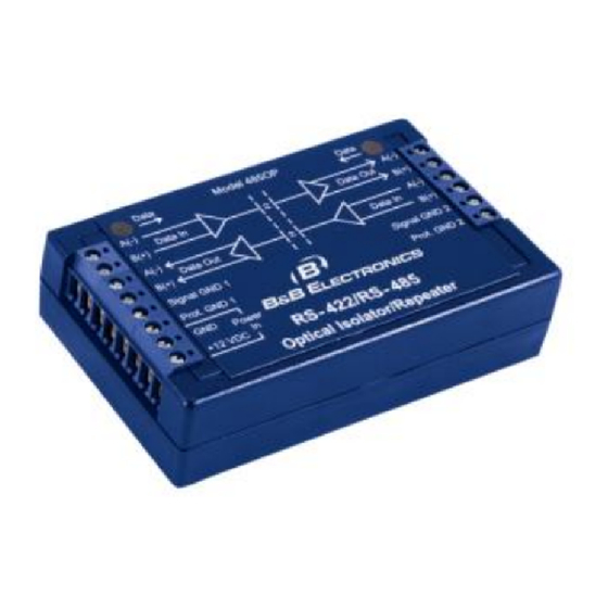
485OP
Optically Isolated RS-422/485
Repeater
1
C
C
h
h
e
e
c
c
k
k
f
f
o
o
r
r
A
A
l
l
l
l
R
R
e
e
q
q
u
u
i
i
r
r
e
e
d
d
485OP Optically Isolated Repeater
This Quick Start Guide
12VDC Wall Power Supply with stripped and tinned
leads.
2
U
U
L
L
I
I
n
n
s
s
t
t
a
a
l
l
l
l
a
a
t
t
i
i
o
o
n
n
I
I
n
n
f
f
o
o
r
r
m
m
Underwriters Laboratories Conditions of Acceptability –
When installed in the end-use equipment, consideration
should be given to the following:
1. The wiring terminals are suitable for factory wiring only.
2. This device is to be mounted in a suitable enclosure in
the end-product.
3. This device is suitable for operation at a maximum
surrounding air temperature as described in the
documentation.
4. These devices are intended for use in a pollution
degree 2 environment.
Input Voltage: 10 – 14 VDC
Input Power: 1.0 Watt
Wire Range: 22 – 14 AWG
Tightening Torque: 0.5 Nm
Temperature rating of field installed conductors is 105 C
minimum, sized for 60 C ampacity.
Use copper wire only
Maximum surrounding ambient air temperature 55 C
3
I
n
f
o
I
n
f
o
H
H
a
a
r
r
d
d
w
w
a
a
r
r
e
e
Label
a
a
t
t
i
i
o
o
n
n
A(-) Data In
B(+) Data In
A(-) Data Out
B(+) Data Out
Signal GND 1
Prot. GND 1
GND
+12 VDC
A(-) Data Out
B(+) Data Out
A(-) Data In
B(+) Data In
Signal GND 2
Prot. GND 2
–
–
r
m
a
t
i
o
n
T
e
r
m
i
n
a
l
B
l
o
c
k
r
m
a
t
i
o
n
T
e
r
m
i
n
a
l
B
l
o
c
k
Side
Signal
Left
TDA (-) / Data A(-)
Left
TDB(+) / Data B(+)
Left
RDA(-) / Data A(-)
Left
RDB(+) / Data B(+)
Put
Left
Signal Ground
Left
Protected Ground
Left
Power Ground
Left
10 – 14 VDC Power Input
Right
RDA(-) / Data A(-)
Right
RDB(+) / Data B(+)
Right
RDA(-) / Data A(-)
Right
RDB(+) / Data B(+)
Right
Signal Ground
Right
Protected Ground
Documentation Number –p/n 8679R1 485OP-1512qsg
©2010 B&B Electronics Manufacturing Company
4
M
o
d
e
&
C
h
a
r
a
c
t
e
r
T
i
m
M
o
d
e
&
C
h
a
r
a
c
t
e
r
T
i
m
PCB Top
PCB Bottom
Operating Mode
Mode
JP1 & JP3 Position
RS-485 2-Wire (Half Duplex)
Center to Half
RS-484 4-Wire (Full Duplex)
Center to Full
RS-422 (Full Duplex)
Center to Full
Jumpers JP1 and JP3 determine whether the receivers will
be disabled when transmitting (half-duplex) or always
enabled (full duplex). As a general rule, JP1 and JP3
should be in the half-duplex position for two-wire operation
and in the full duplex position for four-wire systems.
e
o
u
t
e
o
u
t
Advertisement

Related Manuals for B&B Electronics 485OP


Summary of Contents for B&B Electronics 485OP
- Page 1 Documentation Number –p/n 8679R1 485OP-1512qsg ©2010 B&B Electronics Manufacturing Company Quick Start Guide 485OP Optically Isolated RS-422/485 Repeater – – & & 485OP Optically Isolated Repeater This Quick Start Guide 12VDC Wall Power Supply with stripped and tinned ...
- Page 2 Protective Ground should go traffic LED is turned on. When the 485OP receives the directly to a local earth ground or chassis ground. If the wiring...
Need help?
Do you have a question about the 485OP and is the answer not in the manual?
Questions and answers