Table of Contents
Advertisement
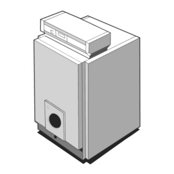
Harrier GT
Installation, Assembly and Servicing
Oil, Gas or Dual Fuel Fired Boilers
Assembly and Installation Instructions for Ideal Harrier Oil, Gas or Dual Fuel Fired heating boilers should be read in
conjunction with the general technical data tables enclosed and any other technical publication supplied with the
burner.
CAUTION. To avoid the possibility of injury during the installation, servicing or cleaning of this appliance care should be taken
when handling edges of sheet steel components.
Advertisement
Table of Contents

Related Manuals for Ideal Boilers Harrier GT


Summary of Contents for Ideal Boilers Harrier GT
- Page 1 Harrier GT Installation, Assembly and Servicing Oil, Gas or Dual Fuel Fired Boilers Assembly and Installation Instructions for Ideal Harrier Oil, Gas or Dual Fuel Fired heating boilers should be read in conjunction with the general technical data tables enclosed and any other technical publication supplied with the burner.
-
Page 2: Table Of Contents
GENERAL INTRODUCTION CONTENTS The Harrier GT boilers are a range of steel shell pressure jet boilers offering high efficiency operation, ease of maintenance, fuel flexibility and low emissions. Suitable for oil or gas operation the Harrier GT range is supplied in a choice of 5 standard models, rated in outputs from 105 kW (358,000 Assembly.................5... -
Page 3: Table Of Contents
1.2 PACKING Harrier GT in bulk ITEM Box No. Harrier GT 5 Harrier GT 6 Harrier GT 7 Harrier GT 8 Harrier GT 9 Front section 8219 - 0002 Intermediate section 8219 - 0001 Rear section... -
Page 4: Installation
6644. The ventilation requirements in this gas fired boiler In these cases, we cannot provide a warranty. standard are also valid for oil fired boilers of the same heat input. Boiler Type Harrier GT 5 Harrier GT 6 Harrier GT 7 Harrier GT 8 Harrier GT 9... -
Page 5: Assembly
Insert the cylinder into the hole provided in each foot of the heating body and screw the adjustable foot into it. Level. 8219-EN-20 ASSEMBLY For the assembly of the boiler, refer to the relevant paragraph of the instruction book. HYDRAULIC CONNECTION 4.1 DIMENSIONAL INFORMATION REQUIRED 8219-EN-17 Harrier GT Range - Installation... -
Page 6: Installation Recommendations
The installer can fit 1/4 turn valve. Draining sludge trap on the return and close to the boiler. sludge involves the loss of significant quantities of water from the system, which must be refilled after the procedure. 8219-EN-19 Harrier GT Range - Installation... -
Page 7: Chimney Connection
INSTALLATION CHIMNEY CONNECTION As the Harrier GT is a high performance boiler, the If necessary, the baffles of the 4 upper smoke chambers may temperature of the flue gases may be less than 160˚C. be partially removed with a resulting increase in temperature The installer ought to take all precautions (padding out, of the flue gases. -
Page 8: Electrical Connection To The Control Panel
The Local Gas Board should be contacted, at a stage prior to actual insallation, for any advice or information required. Details and advice, relating to the use of L.PG. for firing the IDEAL HARRIER GT range of heating boilers, are available on request to Caradon Ideal Ltd. OIL STORAGE TANK The oil storage tank, oil supply pipe and connections to the burner unit MUST comply with the requirements of BS. -
Page 9: Deluxe (Option) - Control Panel
8219-EN-23 • Burner connection Connection of the burner is made using European 7 and 4 pin plugs supplied with the boiler, which simply need to be fitted into the female plugs supplied with the burners. Harrier GT Range - Installation... - Page 10 (3), to the back of the SVR unit: blue connector to the blue plug, red connector to the red plug. - Locate the unit by its front (3) and fix it using the two screws sited in the front part of the equipment (1/4 turn clockwise). Harrier GT Range - Installation...
- Page 11 34 and 37, and 34 and 35 must be removed. - Connect the two connections, situated behind the blank (3), to the back of the SVR unit: blue connector to the blue plug, red connector to the red plug. Harrier GT Range - Installation...
-
Page 12: Standard Control Panel
(if a calorifier is connected). 2. Burner/Heating pump double switch: Switch controlling Where an SVmatic weather compensator is fitted or for a the burner and heating pump. cascade installation, the two switches must be in «Winter» position Harrier GT Range - Installation... - Page 13 SV-matic weather compensator or mounted on the SVR option (this thermostat is pre-set from factory at 80˚C). Harrier GT Range - Installation...
- Page 14 (or of the limit never to set the boiler thermostat under mark 4 (40˚C) so as thermostat in the unique case of the SVR option). to avoid all risk of condensation inside the boiler. Harrier GT Range - Installation...
- Page 15 - Check that the safety thermostat 7 is not tripped. To do this, unscrew the hexagonal cap and using a suitable screw driver, press on the reset button. - Put the burner switch 1 on run. Harrier GT Range - Installation...
-
Page 16: Maintenance
- put the baffles back in place (pay attention to their more, according to the regulations in force. The following direction), operations are always carried out with, the boiler and the - shut the door. power supply shut off. 8219-EN-27 Harrier GT Range - Installation... - Page 17 - brush the inside of the combustion chamber, - close the door and replace the front cover. 8219-EN-62 A 8219-EN-25 A Baffles Harrier GT 5 Harrier GT 6 Harrier GT 7 Harrier GT 8 Harrier GT 9 lg 410...
- Page 18 - If the boiler is going to be stopped for several months we agent to prevent the heating water from freezing. also advise removing the flue connection off the nozzle Otherwise, completely drain the installation. and to close the nozzle with a cover. Harrier GT Range - Installation...
-
Page 19: Technical Data
TECHNICAL DATA 10.1 DATA TABLE General Data Boiler size (no. of sections) Harrier GT 5 Harrier GT 6 Harrier GT 7 Harrier GT 8 Harrier GT 9 Maximum heat output Btu/h x 10 1126 Minimum heat output Btu/h x 10 Combustion chamber 0.122... - Page 20 TECHNICAL DATA 10.2 MAIN DIMENSIONS Harrier GT Range - Installation...
- Page 21 (see § 2.2 of this length of the burner (see instructions § 2.1) document). 8219-EN-28 BP 7 à/to 12 - Clean bores and nipples with a diluent. Coat them with the lubricant provided with the sections. 8219-EN-29 Harrier GT Range - Installation...
- Page 22 Drive in the 8219-EN-30 A Harrier GT Range - Installation...
- Page 23 - Fit the three assembly rods (with dia.12 washer and H12 nuts - 19 mm spanner). The washers are to be found in the covering pack (tightening torque 10 Nm). - Remove the assembly tool. 8219-EN-35 C Harrier GT Range - Installation...
- Page 24 (19 mm spanner). The shorter thread is to be screwed spanner) on the 2 lower studs. into the section. - Put the burner door into place with its pin D. A = M 12 x 50 B = M 12 x 80 8219-EN-39 B Harrier GT Range - Installation...
- Page 25 2 lower pins using 2 H 12 nuts and - Fasten the burner door B with 4 H12 nuts and CL 14 washers - 19 mm spanner. washers. - Put the sweeping door into place along with its pin D. 8219-EN-40 B Harrier GT Range - Installation...
- Page 26 Pay attention to the way to place the baffles 8219-EN 62 A 8219N3 Baffles Table Upper Baffles Flue Ways Harrier GT 5 Harrier GT 6 Harrier GT 7 Harrier GT 8 Harrier GT 9 - lg 410 - lg 570...
- Page 27 14 MOUNTING OF LOWER BAFFLES 8219-EN 62 A 8219-EN 40 B 8219N5 8219N4 Baffles Table Lower Baffles Harrier GT 5 Harrier GT 6 Harrier GT 7 Harrier GT 8 Harrier GT 9 - lg 412 - lg 572 - Break all the stops of the baffles using a mallet for - Close and fasten the door (4 H 12 nuts + 4 L 12N thick instance, except the stop at the front (see figure).
- Page 28 4 M8 x 12 - Fit the rear insulation and hold it in place using clips as bolts and 4 DE8 lockwashers - 13 mm spanner. per the diagram. 8219-EN-44 8219-EN-45 A Harrier GT Range - Installation...
- Page 29 - Put the upper rear panel into position (6 clips). - Put the lower rear panel into position (4 self tapping screws dia. 3.9 x 12.7 + DE4 lockwashers - cross head screwdriver). 8219-EN-54 A Harrier GT Range - Installation...
- Page 30 (if it is too long, push it back between the front panel and the insulation). 8219-EN-49 Harrier GT Range - Installation...
- Page 31 - Screw the side panels to the angle brackets (2 DE5 lockwashers + M5 bolts - 8 mm spanner). The burner cable must pass behind the angle bracket. 8219-EN-50 - Attach the lower cable - cut it if necessary. 8219-EN-51 Harrier GT Range - Installation...
- Page 32 3.94 x 12.7 + lockwashers front top cover Insert them into the small pocket and (cross head screwdriver). maintain them there with the use of a spring. 8219-EN-53 Harrier GT Range - Installation...
- Page 33 DIEMATIC. Close provided for this purpose inside of the control panel. See the control panel (2 self-tapping screws + lockwashers). chapter 7 of the instructions for the standard and E control Harrier GT Range - Installation...
- Page 34 ASSEMBLY - Hook on the front panel. 8219-EN-55 - Hook on the rear front cover and fasten it at the rear using two self-trapping screws of dia. 3.9 x 12.7 + DE4 lockwashers. 8219-EN-56 A Harrier GT Range - Installation...
- Page 35 ASSEMBLY STANDARD CONTROL PANEL - HARRIER ES Harrier GT Range - Installation...
- Page 36 ASSEMBLY DELUXE CONTROL PANEL - HARRIER ES Harrier GT Range - Installation...
- Page 37 (used for modulating burners only). No (1) B5 Feed to 2nd stage operating indicator from burner high fire control to boiler panel. Indicates high fire in operation. Essentially feed back from live on No (3) T8. Earth. Harrier GT Range - Installation...
- Page 38 ?????????? NOTES Harrier GT Range - Installation...
- Page 39 ?????????? NOTES Harrier GT Range - Installation...
- Page 40 Caradon Plumbing Limited Technical Training pursues a policy of continuing improvement in the design and The Caradon Plumbing Limited Technical Training Centre performance of its products. offers a series of first class training courses for domestic, The right is therefore reserved to commercial and industrial heating installers, engineers and vary specification without notice.
Need help?
Do you have a question about the Harrier GT and is the answer not in the manual?
Questions and answers