
Related Manuals for ASROCK 775S61


Summary of Contents for ASROCK 775S61
-
Page 1: User Manual
775S61 User Manual Version 1.0 Published September 2004 Copyright©2004 ASRock INC. All rights reserved. -
Page 2: Copyright Notice
(including damages for loss of profits, loss of business, loss of data, interruption of business and the like), even if ASRock has been advised of the possibility of such damages arising from any defect or error in the manual or product. -
Page 3: Table Of Contents
4.2.1 Running Support CD ..........22 4.2.2 Drivers Menu ............22 4.2.3 Utilities Menu ............22 4.2.4 ASRock “PC-DIY Live Demo” Program ....22 4.2.5 “LGA 775 CPU Installation Live Demo” Program..22 4.2.6 Contact Information ..........22 Appendix ............23 1. -
Page 4: Introduction
(Micro ATX Form Factor: 9.6-in x 9.0-in, 24.4 cm x 22.9 cm) ASRock 775S61 Quick Installation Guide ASRock 775S61 Support CD (including LGA 775 CPU Installation Live Demo) One 80-conductor Ultra ATA 66/100/133 IDE Ribbon Cable One Ribbon Cable for a 3.5-in Floppy Drive... -
Page 5: Specifications
LAN: Speed: 802.3u (10/100 Ethernet), supports Wake-On-LAN Hardware Monitor: CPU temperature sensing; Chassis temperature sensing; CPU overheat shutdown to protect CPU life (ASRock U-COP) (see CAUTION 2); CPU fan tachometer; Chassis fan tachometer; Voltage monitoring: +12V, +5V, +3.3V, Vcore PCI slots: 3 slots with PCI Specification 2.2, PCI3 slot shared with AMR... - Page 6 To improve heat dissipation, remember to spray thermal grease between the CPU and the heatsink when you install the PC system. Do NOT use a 3.3V AGP card on the AGP slot of 775S61 motherboard! It may cause permanent damage! ®...
-
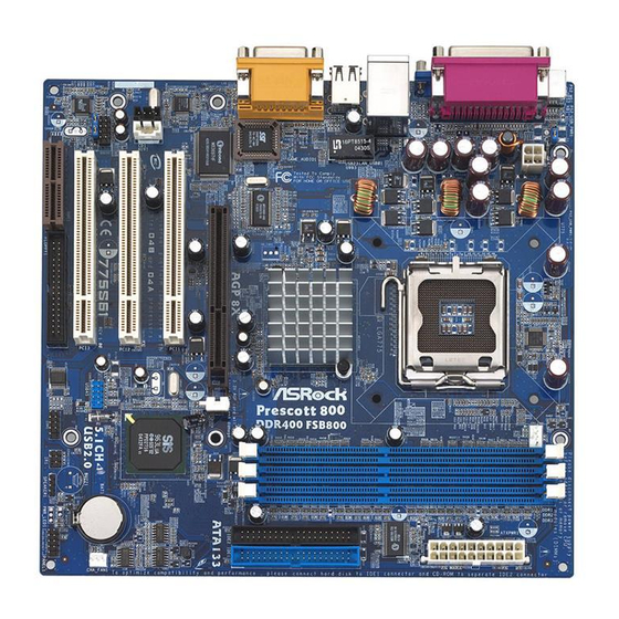
Page 7: Motherboard Layout
Line out Chipset Line Line in BIOS Mic in 1.5V_AGP1 IDE2 IDE1 ATA133 PCI 1 963L PCI 2 CD1 AUX1 AUDIO1 775S61 CMOS 5.1CH USB45 USB2.0 Battery PCI 3 AUDIO CODEC PANEL 1 PLED PWRBTN SPEAKER1 AMR1 HDLED RST COM1... -
Page 8: Asrock I/O
1.4 ASRock I/O Parallel Port Line Out (Lime) RJ-45 Port USB 2.0 Ports Game Port VGA Port Microphone (Pink) PS/2 Keyboard Port (Purple) Line In (Light Blue) PS/2 Mouse Port (Green) -
Page 9: Installation
Chapter 2 Installation 775S61 is a Micro ATX form factor (9.6" x 9.0", 24.4 x 22.9 cm) motherboard. Before you install the motherboard, study the configuration of your chassis to ensure that the motherboard fits into it. Make sure to unplug the power cord before installing or removing the motherboard. -
Page 10: Cpu Installation
2.3 CPU Installation For the installation of Intel 775-Pin CPU, please follow the steps below. 775-Pin Socket Overview Before you insert the 775-Pin CPU into the socket, please check if the CPU surface is unclean or if there is any bent pin on the socket. Do not force to insert the CPU into the socket if above situation is found. - Page 11 For proper inserting, please ensure to match the two orientation key notches of the CPU with the two alignment keys of the socket. Step 2-3. Carefully place the CPU into the socket by using a purely vertical motion. Step 2-4. Verify that the CPU is within the socket and properly mated to the orient keys.
-
Page 12: Installation Of Cpu Fan And Heatsink
Installation of CPU Fan and Heatsink This motherboard is equipped with 775-Pin socket that supports Intel 775-Pin CPU. Please adopt the type of heatsink and cooling fan compliant with Intel 775-Pin CPU to dissipate heat. Before you installed the heatsink, you need to spray thermal interface material between the CPU and the heatsink to improve heat dissipation. -
Page 13: Installation Of Memory Modules (Dimm)
2.5 Installation of Memory Modules (DIMM) 775S61 motherboard provides three 184-pin DDR (Double Data Rate) DIMM slots. Please make sure to disconnect power supply before adding or removing DIMMs or the system components. Step 1. Unlock a DIMM slot by pressing the retaining clips outward. -
Page 14: Expansion Slots
2.6 Expansion Slots (PCI, AMR, and AGP Slots) There are 3 PCI slots, 1 AMR slot, and 1 AGP slot on 775S61 motherboard. PCI slots: The PCI slots are used to install expansion cards that have the 32-bit PCI interface. -
Page 15: Jumpers Setup
2.7 Jumpers Setup The illustration shows how jumpers are setup. When the jumper cap is placed on pins, the jumper is “SHORT”. If no jumper cap is placed on pins, the jumper is “OPEN”. The illustration shows a 3-pin jumper whose pin1 and pin2 are “SHORT”... -
Page 16: Onboard Headers And Connectors
Besides, to optimize compatibility and performance, please connect your hard disk drive to the primary IDE connector (IDE1, blue) and CD-ROM to the secondary IDE connector (IDE2, black). USB 2.0 Header ASRock I/O Plus provides you USB_PWR 6 ready-to-use USB 2.0 ports on... - Page 17 Front Panel Audio Header This is an interface for the front +5VA BACKOUT-R panel audio cable that allows (9-pin AUDIO1) BACKOUT-L convenient connection and (see p.7 item 22) control of audio devices. AUD-OUT-L AUD-OUT-R MIC-POWER System panel connector This connector accommo- PLED+ PLED- PWRBTN#...
-
Page 18: Bios Setup
Chapter 3 BIOS Setup 3.1 BIOS Setup Utility This section explains how to configure your system using the BIOS Setup Utility. The Flash Memory on the motherboard stores the BIOS Setup Utility. When you start up the computer, there is a chance for you to run the BIOS Setup. Press <F2> during the Power-On-Self-Test (POST) to enter the BIOS Setup Utility, otherwise, POST continues with its test routines. -
Page 19: Main Menu
System Time Month: Jan - Dec Day: 01 - 31 Floppy Drives Year: 1980 - 2099 IDE Devices BIOS Version 775S61 BIOS P1.00 Processor Type Intel (R) CPU Processor Speed 2933 MHz Cache Size 256 KB Microcode Update F41 / 05... - Page 20 TYPE To set the type of the IDE device, first, please select “IDE Devices” on Main menu and press <Enter> to get into the sub-menu. Then, select among “Primary IDE Master”, “Primary IDE Slave”, “Secondary IDE Master”, and “Secondary IDE Slave” to make configuration of its type. Below are the configuration options.
-
Page 21: Advanced, Security, Power, Boot, And Exit Menus
[CD/DVD]: This is used for IDE CD/DVD drives. [ARMD]: This is used for IDE ARMD (ATAPI Removable Media Device), such as MO. Cylinders This is used to configure the number of cylinders. Refer to the drive documentation to determine the correct value. Heads This is used to configure the number of read/write heads. -
Page 22: Software Support
Support CD through the following path: ..\ MPEGAV \ LGA775INST.DAT 4.2.6 Contact Information If you need to contact ASRock or want to know more about ASRock, welcome to visit ASRock’s website at http://www.asrock.com; or you may contact your dealer for further information. -
Page 23: Appendix
Appendix: Advanced BIOS Setup This section will introduce you the following BIOS Setup menus: “Advanced,” “Security,” “Power,” “Boot,” and “Exit.” 1. Advanced BIOS Setup Menu AMIBIOS SETUP UTILITY - VERSION 3.31a Exit Advanced Security Boot Main Power [ Setup Help ] Spread Spectrum Disabled Auto... - Page 24 Chipset Configuration: AMIBIOS SETUP UTILITY - VERSION 3.31a Advanced Chipset Configuration [ Setup Help ] <Enter> to select the AGP Aperture Size 64MB size of mapped memory Onboard VGA Share Memory for graphics data. Auto USB Controller Enabled USB Device Legacy Support Disabled USB 2.0 Controller Enabled...
- Page 25 No-Excute Memory Protection: No-Execution (NX) Memory Protection Tech nology is an enhancement to the IA-32 Intel Architecture. An IA-32 proces sor with “No Execute (NX) Memory Protection” can prevent data pages from being used by malicious software to execute code. This option will be hidden if the current CPU does not support No-Excute Memory Protection.
-
Page 26: Resource Configuration
Resource Configuration: AMIBIOS SETUP UTILITY - VERSION 3.31a Advanced Resource Configuration [ Setup Help ] <Enter> to select PCI PCI Latency Timer (PCI Clocks) clocks. Leave on Primary Graphics Adapter default setting for the best PCI performance. F1:Help F9:Setup Defaults :Select Item +/-:Change Values Esc:Previous Menu... - Page 27 OnBoard Parallel Port: Select Parallel Port address or disable Parallel Port. Configuration options: [Auto], [Disabled], [378], [278]. Parallel Port Mode: Set the operation mode of the parallel port. The default value is [ECP+EPP]. If this option is set to [ECP+EPP], it will show the EPP version in the following item, “EPP Version”.
-
Page 28: Security Setup Menu
2. Security Setup Menu AMIBIOS SETUP UTILITY - VERSION 3.31a Boot Exit Advanced Security Power Main [ Setup Help ] Clear Supervisor Password Clear User Password <Enter> to set the supervisor password. [ Enter ] Set Supervisor Password [ Enter ] Set User Password Setup Password Check... -
Page 29: Power Setup Menu
3. Power Setup Menu AMIBIOS SETUP UTILITY - VERSION 3.31a Exit Advanced Security Boot Main Power [ Setup Help ] Suspend To RAM (S3) Disabled Repost Video on S3 Resume Disabled Set the power state Restore on AC / Power Loss Power Off after an unexpected Ring-In Power On... -
Page 30: Boot Setup Menu
4. Boot Setup Menu AMIBIOS SETUP UTILITY - VERSION 3.31a Security Boot Exit Advanced Power Main [ Setup Help ] Quick Boot Mode Enabled Boot Up Num-Lock <Enter> to enable or Boot To OS/2 disable the quick boot Boot From Network Disabled mode. -
Page 31: Exit Menu
5. Exit Menu AMIBIOS SETUP UTILITY - VERSION 3.31a Security Boot Exit Advanced Power Main [ Setup Help ] [ Enter ] Exit Saving Changes [ Enter ] Exit Discarding Changes Exits and saves the [ Enter ] Load Default Settings changes to CMOS RAM [ Enter ] Discard Changes...
Need help?
Do you have a question about the 775S61 and is the answer not in the manual?
Questions and answers