
Related Manuals for A.H. Systems SAS-517


Summary of Contents for A.H. Systems SAS-517
- Page 1 A.H. Systems SAS-517 Log Periodic Antenna SAS-517 Log Periodic Antenna Operation Manual A.H. Systems inc. – May 2014 REV C...
-
Page 2: Table Of Contents
A.H. Systems SAS-517 Log Periodic Antenna TABLE OF CONTENTS INTRODUCTION Introduction ......................3 Intended Purposes....................4 Optional Equipment....................5 OPERATING INSTRUCTIONS Assembly Instructions ..................... 6 Mounting Instructions....................6 Operating Instructions....................8 SPECIFICATIONS Specifications ......................9 Typical Data......................10 Calculations......................12 Convertion Factors....................13... -
Page 3: Introduction
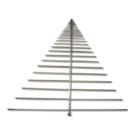
A.H. Systems SAS-517 Log Periodic Antenna INTRODUCTION The SAS-517 Log Periodic Antenna (also known as a log periodic dipole array) is a lightweight antenna that has been designed to ensure medium gain, low VSWR and high power handling capabilities. Constructed of lightweight aluminum, the SAS-517 Log Periodic Antenna has been manufactured to operate over a very wide bandwidth. -
Page 4: Intended Purposes
A.H. Systems SAS-517 Log Periodic Antenna INTENDED PURPOSES The log periodic antenna is intended for general laboratory use in a wide variety of industrial and scientific applications and has been designed to be used in the process of generating, controlling and measuring high levels of electromagnetic Radio Frequency (RF) energy. -
Page 5: Optional Equipment
A.H. Systems SAS-517 Log Periodic Antenna OPTIONAL EQUIPMENT The following is a recommend accessory list for the SAS-517 Log Periodic Antenna: CONNECTING ACCESSORIES: PAM-0204 This preamplifier has a broad frequency range and at least 22 dB of gain. An ideal solution for improving overall system sensitivity for various emissions testing requirements. -
Page 6: Assembly Instructions
MOUNTING INSTRUCTIONS The SAS-517 is a lightweight, rear mount or mid mount via the LPM-510 Log Periodic Antenna. Attach the antenna to the azimuth and elevation head (AEH- 510) through the screw hole in the antenna base. The azimuth and elevation head (AEH-510) mounts to the tripod (ATU-510) top and allows the antennas to be rotated 360 degrees and tilted between horizontal and vertical polarization. - Page 7 A.H. Systems SAS-517 Log Periodic Antenna EMISSIONS TESTING MEASUREMENT POINT: For 3 and 10 meter testing, the measurement is made from the center of the antenna radiating elements and is annotated by a measurement point sticker (per ANSI C63.5). IMMUNITY TESTING MEASUREMENT POINT: Measurement is made from the tip of the antenna and typically preformed at a 1 meter distance.
-
Page 8: Operating Instructions
A.H. Systems SAS-517 Log Periodic Antenna OPERATING INSTRUCTIONS Once the antenna is mounted to a mast or tripod, connect an N-type coaxial cable from the antenna to a receiver or RF generator. The cable should be matched to 50 ohms, relatively low loss and adequately shielded against leakage such as RG-214/U or better. -
Page 9: Specifications
A.H. Systems SAS-517 Log Periodic Antenna SPECIFICATIONS ELECTRICAL SPECIFICATIONS Frequency Range ................80 MHz – 4 GHz Antenna Factor..................6 to 36 dB/m Antenna Gain....................6.4 dBi Maximum Continuous Power..............1000 Watts Average Beamwidth.....................45° Average Beamwidth (H-Field)................100° Impedance (nominal)..................50W Average VSWR................... 1.4:1 typ. -
Page 10: Typical Data
A.H. Systems SAS-517 Log Periodic Antenna TYPICAL DATA A.H. Systems inc. – May 2014 REV C... - Page 11 A.H. Systems SAS-517 Log Periodic Antenna A.H. Systems inc. – May 2014 REV C...
-
Page 12: Calculations
A.H. Systems SAS-517 Log Periodic Antenna CALCULATIONS EMISSIONS TESTING Individual calibration data for the log periodic antenna is supplied at appropriate distances (3, and 10 meter) to comply with various emissions test requirements. For emissions measurements, add antenna factor plus cable loss to receiver reading in dBV to convert to field strength in dBV/meter. -
Page 13: Convertion Factors
A.H. Systems SAS-517 Log Periodic Antenna TYPICAL CONVERSION FORMULAS LOG -> LINEAR VOLTAGE FIELD STRENGTH & POWER DENSITY ((dB V – 120) / 20) dBV to Volts V = 10 dBV/m to V/m V/m = 10 (((dBV/m) -120) / 20) Volts to dBV... -
Page 14: Maintenance
ANNUAL CALIBRATION To ensure reliable and repeatable long-term performance, annual re-calibration of your antennas, preamplifiers and current probes by A.H. Systems experienced technicians is recommended. Our staff can calibrate almost any type or brand of antenna. It is always up to the user to determine the appropriate interval for calibration certification based on the requirements of the end users specific test/application. -
Page 15: Warranty
A.H. Systems SAS-517 Log Periodic Antenna WARRANTY INFORMATION A.H. Systems Inc., warrants that our Antennas, Sensors and Probes will be free from defects in materials and workmanship for a period of three (3) years. All other products delivered under contract will be warranted for a period of two (2) years. Damage caused by excessive signals at the product's input is not covered under the warranty.
Need help?
Do you have a question about the SAS-517 and is the answer not in the manual?
Questions and answers