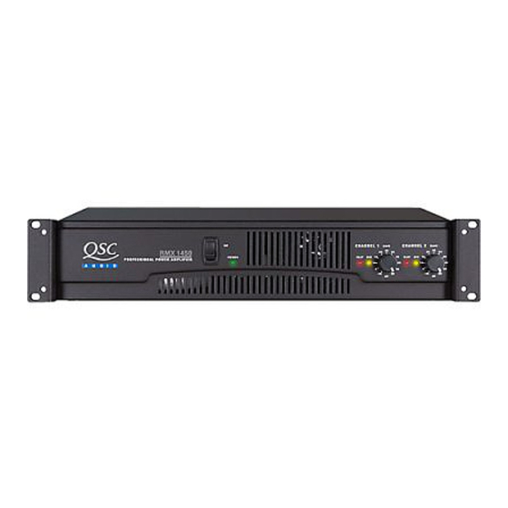
QSC RMX 850 Service Bulletin
Rmx series amplifiers
Hide thumbs
Also See for RMX 850:
- Technical & service manual (42 pages) ,
- User manual (38 pages) ,
- Specifications (6 pages)
Table of Contents
Advertisement
Quick Links
Description
Some RMX Series amplifiers take longer than 10 seconds to fully turn on. This is caused by the 5.6-volt zener diodes (D107,
D110, D207, and D210) in the bias circuitry causing the op amps to remain in non-symmetrical cutback even after turn-on
muting ends. The channel bias will take perhaps 10 to 30 seconds to set before the amplifier begins working normally.
This bulletin describes a corrective procedure that involves replacing the original zeners with 4.7-volt diodes and 180Ω
resistors to improve op-amp turn-on.
Symptoms
After the amplifier is turned on, both channels' clip LEDs remain lit for more than 10 seconds. This occurs only when speaker
loads are attached to the amplifier outputs.
Instructions
Tools and materials required:
• Soldering iron with fine tip (recommended range 25 to 60 W)
• Rosin-core solder (60/40 or 63/37 eutectic type)
• Long-nose pliers
• #1 and #2 Philips screwdrivers
• Small diagonal cutters
• Desoldering equipment or solder braid
• Four 4.7V zener diodes (QSC part # QD-0004.7-ZT) and four 180Ω ¼W 5% resistors per RMX amplifier
Test equipment required:
• Oscilloscope
• 2-ohm resistive load (rated for at least 1200 watts)
• Shorting connector for amplifier output
• Variable AC transformer (e.g., Variac, Powerstat, etc.) rated for 25A (120V) or 12A (230V). Make sure the amplifier and your
AC supply are compatible.
• 1 kHz audio sine wave generator
• Digital multimeter
• Digital current meter (e.g., Fluke 30 Clamp Meter)
• Trimpot adjustment tool (non-conductive)
Procedure: replacing the zener diodes
The RMX 850 and RMX 1450 use single-sided printed circuit boards, so replacing the zener diodes requires removal of the
two channel module boards from the chassis. The RMX 2450 uses double-sided boards with plated-through holes, so zener
replacement can be done while working from the top side of the board, and removing the channel modules is unnecessary.
Preliminary work
1.
Disconnect the amplifier from the AC service and wait several minutes to let internal voltages bleed down.
2.
Remove the top cover.
RMX 2450
1.
Locate diodes D107 and D110. See Figure 1.
2.
With the diagonal cutters, clip out the body of the diodes.
RMX0002
RMX Turn-on Delay
Title:
Bulletin #:
RMX0002
Models Affected: RMX 850, 1450 & 2450
Production Range: 01/2000–08/2000
Service Bulletin
Issue Date:
Bulletin Revision: A
September 28, 2000
1
Advertisement
Table of Contents

Summary of Contents for QSC RMX 850
-
Page 1: Service Bulletin
Procedure: replacing the zener diodes The RMX 850 and RMX 1450 use single-sided printed circuit boards, so replacing the zener diodes requires removal of the two channel module boards from the chassis. The RMX 2450 uses double-sided boards with plated-through holes, so zener replacement can be done while working from the top side of the board, and removing the channel modules is unnecessary. - Page 2 R246 in the RMX 2450. Note that in this model, the positions of channel 1 and 2’s channel modules are the reverse of where they are in the RMX 850 and RMX 1450. With long-nose pliers, hold one of the lead remnants. Melt the solder with the iron, then pull the lead out of the circuit board.
- Page 3 The components for channel 2 are similarly located 13. Continue with bias and current limiting adjustments. on the other channel module. The model shown is an RMX 1450, but the RMX 850’s components are located in the same places. Procedure: bias and current-limiting calibration Note: During the current-limiting part of this procedure, the amplifier will draw high amounts of AC: approximately 22 amperes at 120V, or 11 amperes at 230V.
-
Page 4: Contact Information
Turn the amp off and disconnect all cables. Re-install the top cover. The amplifier may now be returned to use. Contact information If you need any further information regarding this service procedure, please contact QSC Technical Services at the addresses or numbers below. Telephone:...


Need help?
Do you have a question about the RMX 850 and is the answer not in the manual?
Questions and answers