Samsung S1050 Service Manual
Hide thumbs
Also See for S1050:
- User manual (102 pages) ,
- Manual de usuario (100 pages) ,
- Specifications (12 pages)
Table of Contents
Advertisement
Quick Links
Advertisement
Chapters
Table of Contents

Related Manuals for Samsung S1050


Summary of Contents for Samsung S1050
-
Page 2: Table Of Contents
C O N T E N T S Ⅰ Ⅰ . SPECIFICATION 1. CAMERA SPECIFICATION ………………………………………………………………………………………4 2. SYSTEM REQUIREMENTS …………………………………………………………………………………… 7 3. TFT LCD PANEL MARK …………………………………………………………………………………………8 4. CONNECTION DIAGRAM ……………………………………………………………………………………… 11 5. IDENTIFICATION OF FEATURES ………………………………………………………………………………12 Ⅱ Ⅱ . . EXPLODED VIEW AND PARTS LIST 1. - Page 3 Ⅴ Ⅴ . . C C I I R R C C U U I I T T D D I I A A G G R R A A M M ………………………………………………………………………………………………………… 121 1) MAIN …………………………………………………………………………………………………… 122 2) MAIN_DDR ……………………………………………………………………………………………...
-
Page 4: Camera Specification
Ⅰ. SPECIFICATION 1. CAMERA SPECIFICATION Image Sensor - Type : 1/1.8" CCD - Effective Pixel : Approx.10.1 Mega-pixel - Total Pixel : Approx. 10.3 Mega-pixel Lens - Focal Length : SHD Lens f = 7.8~39mm (35mm film equivalent : 38~190mm) - F No. - Page 5 ·Movie Clip : AVI (MJPEG) ·Audio : WAV - Image Size 3648x2432 3072x2304 2592x1944 2048x1536 1024x768 3648x2736 3648x2052 - Capacity (256 MB MMC) ※ These figures are measured under Samsung’s standard conditions and may vary depending on shooting conditions and camera settings.
- Page 6 Ⅰ. SPECIFICATION “ “ E” ” Button - Effect : Color, Image Adjust, Fun (Highlight, Composite, Photo Frame) - Editing : Resize, Rotate, Color, Special Color, Image Adjust (Red eye fix, Brightness, Contrast, Saturation, Add Noise), Fun (Cartoon, Highlight, Composite, Photo Frame, Sticker) Image Play - Single image, Thumbnails, Slide show, Movie Clip Interface...
-
Page 7: System Requirements
Ⅰ. SPECIFICATION 2. System Requirements For Windows For Macintosh PC with processor better than Pentium II 450MHz Power Mac G3 or later (Pentium 700MHz recommended) Windows 98SE/2000/ME/XP/Vista Mac OS 9.2 ~ 10.3 Minimum 64MB RAM Minimum 64MB RAM 200MB of available hard disk space 110MB of available hard-disk space USB port USB port... - Page 8 Ⅰ. SPECIFICATION 3. LCD monitor indicator ■ Recording mode ① ⑳ ⑲ ② ⑱ ③ ⑰ ④ ⑯ ⑤ ⑮ ⑥ ⑭ ⑦ ⑬ ⑧ ⑫ ⑨ ⑩ ⑪ [Image & Full Status]...
- Page 9 Ⅰ. SPECIFICATION Description Icons Recording mode Aperture Value/ Shutter Speed F2.8, 1/30 Face Recognition Flash Self-timer Macro Contrast Sharpness Auto focus frame Camera shake warning Date/ Time 2007/02/01 01:00 PM Exposure compensation White Balance Continuous shot Metering Image quality Image size Battery Optical/ Digital Zoom bar/ Digital Zoom rate Voice memo/ Without Sound...
- Page 10 Ⅰ. SPECIFICATION ■ Play mode ⑬ ⑫ ⑪ ① ② ③ ⑩ ④ ⑨ F2.8 ⑧ 1/250 ⑦ FLASH ⑥ SIZE 3648X2736 ⑤ DATE 2007/02/01 Description Icon Play mode icon Voice Memo Protect DPOF Recording date 2007/02/01 Image size 3648X2736 ~ 256X192 Flash ON/OFF Shutter speed...
- Page 11 Ⅰ. SPECIFICATION 4 4 . . C C O O N N N N E E C C T T I I O O N N D D I I A A G G R R A A M M SD Card Card Reader Lap top...
-
Page 12: Identification Of Features
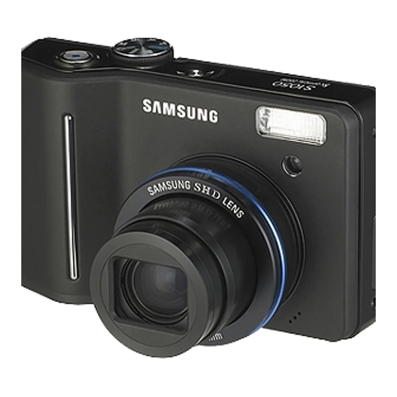
Ⅰ. SPECIFICATION 5. IDENTIFICATION OF FEATURES Front & Top Modedial Power button Shutter button Speaker Flash Self-timer lamp / Auto focus lamp USB / AV connection terminal DC input connection port Lens/ Lens cover Microphone Back & Bottom Camera status lamp Zoom T button (Digital zoom) Zoom W button... -
Page 13: Function Button
Ⅰ. SPECIFICATION Bottom Battery chamber cover Battery chamber Memory card slot 5-function button Voice memo/ Voice Recording/ Up button Menu/ OK button Flash/ Self-timer/ Left button Right button Macro/ Down button Play & Pause button... -
Page 14: Main Assembly
Ⅱ. EXPLODED VIEW AND PART LIST 1. MAIN ASSEMBLY... - Page 15 Ⅱ. EXPLODED VIEW AND PART LIST ▶ PARTS LIST Fig.No Parts No. Parts Name Q’ty Supply Available Parts Remarks Q7409279801A PCB SHIELD FORM Q6001016501A SCREW Q7217398301A BOTTOM DECO Q6003002402A SCREW Q6003002702A SCREW Q7104002401A MODE DIAL DECO...
-
Page 16: Body Assembly
Ⅱ. EXPLODED VIEW AND PART LIST 2. BODY ASSEMBLY 2-31 2-21 2-24 2-17 2-15 2-14 2-13 2-16 2-12 2-10 2-31 2-20 2-13 2-18 2-19 2-11 2-31 2-30 2-13 2-30 2-28 2-26 2-27 2-23 2-25 2-31... - Page 17 Ⅱ. EXPLODED VIEW AND PART LIST ▶ ▶ PARTS LIST Fig.No Parts No. Parts Name Q’ty Supply Available Parts Remarks Q7211088602A BATTERY CHAMBER Q7011055603A BATTERY CONTACT(S2_5363) Q7003000402A TRIPOD CONNECTOR Q9761173012 SCREW Q9007278601A BATTERY COVER ASSY BLACK Q9007278601B BATTERY COVER ASSY SILVER Q9007278601C BATTERY COVER ASSY...
-
Page 18: Barrel Assembly
Ⅱ. EXPLODED VIEW AND PART LIST 3. BARREL ASSEMBLY 3-15 3-16 3-17 3-44 3-20 3-13 3-12 3-11 3-10 3-13 3-14 3-19 3-29 3-28 3-26 3-27 3-24 3-42 3-25 3-23 3-22 3-21 3-41 3-33 3-40 3-38 3-39 3-36 3-35 3-34 3-33 3-32 3-31 3-43... - Page 19 Ⅱ. EXPLODED VIEW AND PART LIST ▶ PARTS LIST Fig.No Parts No. Parts Name Q’ty Supply Available Parts Remarks AF MOTOR ASS'Y Q9002145901A Q4101039101A MAIN_F-PCB Q0608001301A PHOTO INTERRUPTER SHARP Q9002159601A MAIN_F-PCB_ASSY Q0608001001A PHOTO INTERRUPTER Q9002159801A BARREL_ASSY Q0961900301A SCREW Q7212192602A AF GUIDE HOLDER Q7012080802A AF CLIP HOLDER 3-10...
- Page 20 Ⅱ. EXPLODED VIEW AND PART LIST ▶ PARTS LIST Fig.No Parts No. Parts Name Q’ty Supply Available Parts Remarks 3-21 Q7409208602B 1ST SHIELD 1ST BARREL ASS'Y 3-22 Q9002142901A 3-23 Q7212192101A SLIP RING 3-24 Q7012094101A CAM_DECO_RING 3-25 Q7212197502A ZOOM_RING 3-26 Q7411110404A 1ST MOVE PIN 3-27 Q7212197401A...
- Page 21 Ⅱ. EXPLODED VIEW AND PART LIST ▶ PARTS LIST Fig.No Parts No. Parts Name Q’ty Supply Available Parts Remarks 3-34 Q6107066103B 2ND LENS SPRING SHUTTER ASS'Y 3-35 Q9005163201A 3-36 Q9002143101A 3RD BARREL ASS'Y 3-37 Q7411121704A 2ND MOVE PN 3-38 Q7012088701A 3RD LIGHT SHIELD 3-39 Q7212191901A...
-
Page 22: Barrier Assembly
Ⅱ. EXPLODED VIEW AND PART LIST 4. BARRIER ASSEMBLY 4-11 4-12... - Page 23 Ⅱ. EXPLODED VIEW AND PART LIST ▶ PARTS LIST Fig.No Parts No. Parts Name Q’ty Supply Available Parts Remarks Q7012094001A DECORATION_RING BLACK Q7012098101A DECORATION_RING SILVER Q6003048701A BARRIER SCREW-A Q7212192805A FRONT PANEL Q7212193102A BARRIER C Q6107066302A BARRIER_CLOSE_SPRING Q7212192902A BARRIER A Q7212193002A BARRIER B Q7012087703B BARRIER BASE...
-
Page 24: Strobo Assembly
Ⅱ. EXPLODED VIEW AND PART LIST 5. STROBO ASSEMBLY... - Page 25 Ⅱ. EXPLODED VIEW AND PART LIST ▶ PARTS LIST Fig.No Parts No. Parts Name Q’ty Supply Available Parts Remarks Q9008115901A STROBO FPCB ASS'Y Q7214091101A REFLECTOR HOLDER Q7309048001A XE TUBE RUBBER Q7011056002A TRIGER CONTACT Q7014004801A REFLECTOR Q0611003101A REF XE TUBE Q7214091001A FRESNEL LENS Q0961900301A SCREW...
-
Page 26: Front Cover Assembly
Ⅱ. EXPLODED VIEW AND PART LIST 6. FRONT COVER ASSEMBLY 6-21 6-24 6-20 6-23 6-19 6-18 6-22 6-32 6-33 6-16 6-26 6-25 6-27 6-17 6-30 6-14 6-29 6-28 6-31 6-27 6-15 6-14 6-10 6-11 6-12... - Page 27 6-29 Q7011060101A TOP KEY PLATE 6-30 Q3001001501A SPEAKER 6-31 Q9007278501A TOP KEY PLATE ASSY Q9007277501A MIDDLE COVER ASSY KENOX S1050 BLACK Q9007277501C MIDDLE COVER ASSY KENOX S1051 SILVER 6-32 Q9007277501B MIDDLE COVER ASSY_SAMSUNG S1050 BLACK Q9007277501D MIDDLE COVER ASSY_SAMSUNG S1050...
-
Page 28: Rear Cover Assembly
Ⅱ. EXPLODED VIEW AND PART LIST 7. REAR COVER ASSEMBLY 7-19 7-16 7-13 7-14 7-15 7-11 7-12 7-18 7-10... - Page 29 Ⅱ. EXPLODED VIEW AND PART LIST ▶ ▶ PARTS LIST Fig.No Parts No. Parts Name Q’ty Supply Available Parts Remarks Q7101003301C BACK AL COVER Q7103004201A STRAP HOLDER BLACK Q7103004201B STRAP HOLDER SILVER Q7101003401A STRAP HOLDER PLATE Q6001018801A SCREW Q7409268001A BACK LED TAPE Q7217398001A BACK LED WINDOW Q7409268101A...
-
Page 30: Packing Item
Ⅱ. EXPLODED VIEW AND PART LIST 8. PACKING ITEM 8-19 8-12 8-18 8-20 8-14 8-15 8-16 8-10 8-11 8-13... - Page 31 Ⅱ. EXPLODED VIEW AND PART LIST ▶ ▶ PARTS LIST Fig.No Parts No. Parts Name Q’ty Supply Available Parts Remarks QP960210101A PE BAG (FOR CAMERA) Q6909018202A PE BAG (FOR ACCESSORY) Q6901266101A MOLD_PULP_Samsung_S1050_EXP Q7409271401A STRAP_KENOX_S730_KOR_EXP Q4609018301A DRIVER_DIGIMAX_MASTER_S3-105 Q6909020201A AIR_BAG_Samsung_S1050_FOR_BODY Q6909020101A AIR_BAG_KENOX_S1050 Q6806381001A Q_GUIDE_KENOX_S1050 Q6806381301A...
- Page 32 Ⅱ. EXPLODED VIEW AND PART LIST ▶ ▶ PARTS LIST Fig.No Parts No. Parts Name Q’ty Supply Available Parts Remarks Q6806381101A U_MANUAL_KENOX_S1050 Q6806383001A U_MANUAL_Samsung_S1050_ENG Q6806383101A U_MANUAL_Samsung_S1050_GER Q6806383201A U_MANUAL_Samsung_S1050_FRA Q6806383301A U_MANUAL_Samsung_S1050_SPA Q6806383401A U_MANUAL_Samsung_S1050_ITA Q6806383501A U_MANUAL_Samsung_S1050_CHI_T Q6806383601A U_MANUAL_Samsung_S1050_DUT Q6806383701A U_MANUAL_Samsung_S1050_POR Q6806383801A U_MANUAL_Samsung_S1050_SWE Q6806383901A U_MANUAL_Samsung_S1050_DEN Q6806384001A...
- Page 33 Ⅱ. EXPLODED VIEW AND PART LIST ▶ ▶ PARTS LIST Fig.No Parts No. Parts Name Q’ty Supply Available Parts Remarks QP955150101F WARRANTY CARD_KOREA Q6807003003U WARRANTY CARD_EXP Q6807012301A WARRANTY CARD_2 YERARS Q6807010903C WARRANTY CARD_RUS(3 YEARS) 8-10 Q6807011301B WARRANTY CARD_TSOE(CHINA) Q6807009502E CARD_PRODUCT(Mexico) Q6807012101A WARRANTY CARD_IRAN Q6807012401A...
-
Page 34: Firmware
Ⅲ. ADJUSTMENT 1. FIRMWARE 1) Reseting Camera 1. Turn on the Camera 2. Press and hold the UP button and Shutter button and then press the Power button. - Page 35 Ⅲ. ADJUSTMENT 3. Turn on the camera and check whether the camera is reset or not.
- Page 36 Ⅲ. ADJUSTMENT 2) Checking version 1. Remove the memory card from the camera. 2. Turn on the camera.
- Page 37 Ⅲ. ADJUSTMENT 3. Turn on the camera and press the Up button twice. 4. Press the 5 function button as following order. (Left button → Right button → Down button → +/- button)
- Page 38 Ⅲ. ADJUSTMENT 5. After pressing the buttons, Firmware version will be displayed...
- Page 39 Ⅲ. ADJUSTMENT 3) Upgrading 1. Insert the SD card that has the firmware and turn on the camera. * Updating the firmware will delete all data in the SD card. Be sure to download all data to your PC before updating the firmware. The firmware file name must be "...
- Page 40 Ⅲ. ADJUSTMENT 4. Press the Up button twice to select the Voice recording mode 5. Press the 5 function button as following order. (Left button → Right button → UpÄbutton → +/- button)
- Page 41 Ⅲ. ADJUSTMENT 6. After pressing the buttons, Firmware upgrading is shown and then the firmware will be upgraded. (For about 30 seconds. Camera status lamp : blicking) 7. After upgrading the firmware, the camera will be turned off automatically. 8. Turn on the camera and do the 'Reset' menu in the Setup menu...
- Page 42 Ⅲ. ADJUSTMENT 4) Full Version of Firmware How to do the Full Version of Firmware Depend on the camera status If the Full version of Firmware is needed, upgrade the Full Version of Firmware. ▷Camera Status : When turning on the camera, the power consumption (Checking the POWER SUPPLY) is 200-300mA and the camera can't be operated ▷Cause : The data of 0 address in the FLASH MEMORY of the MAIN PCB is damaged...
- Page 43 Ⅲ. ADJUSTMENT 2. Use the AC adapter or fully charged battery. All of the battery level indicator on the LCD monitor must be displayed. 3. Turn on the camera. 4. Press the Up button twice to select the Voice recording mode. 5.
- Page 44 Ⅲ. ADJUSTMENT 6. After pressing the buttons, Ämessage will display for about 1 minute. (Camera status lamp : blicking)
- Page 45 Ⅲ. ADJUSTMENT - While upgrade the Full Version of firmware, the previous data will be saved into the SD card automatically and there should be 3 files LSCLUT0.BIN, DefectivePixel0.bin and DefectivePixel1.bin when the copy is firmly completed.
- Page 46 Ⅲ. ADJUSTMENT 7. After the Full Version of firmware, upload the back up data. Tun on the camera and press the Up button twice to select the Voice recording mode again. Press the 4Äfunction button as following order. (Telet button → Wide button → Down button → OK button)
- Page 47 Ⅲ. ADJUSTMENT 8. The upload will be completed after below massage is shown. 9. Turn off the camera.(This time, the camera turns off automatically.)
- Page 48 2. ADJUSTMENT CAUTION 1) Basic Information of Adjustment After changing the electronic parts of S1050, the parts have to be adjusted in accordance withe the adjusted items. The items listed on the table are have to be adjusted after changing.
- Page 49 Ⅲ. ADJUSTMENT 3> Adjustment program file To adjust all items, all kinds of code by items have to be inserted in program file and saved them to the SD card as TXT file type. The codes are listed below < Description of TXT file > Use the Memo pad of Basic Windows program and save it as "STS3105ADJ.txt".
- Page 50 Ⅲ. ADJUSTMENT //delay 5 //adj_control signal 100 //======================================#2.LSC //mode program adj_lens_shading ng_repeat 3 adj_lens_shading lut_load_percent 80 adj_lens_shading before_capture_skip 1 adj_lens_shading luma_min_max 75 120 adj_lens_shading run //delay 5 //adj_control signal 100 //======================================#3.Battery Level adj_battery base 211 231 ...
-
Page 51: Strobo
Ⅲ. ADJUSTMENT //======================================#5.Shutter Closing zoom close_to_open mode program adj_sh_close max_count 20 adj_sh_close open_init_linedelay 40 adj_sh_close open_init_subdelay 0 adj_sh_close open_linedelay_min_max 35 55 adj_sh_close apt_init_linedelay 43 adj_sh_close apt_init_subdelay 0 adj_sh_close apt_linedelay_min_max 40 60 adj_sh_close iris_skip 0 adj_sh_close iris_adjustrange 6 ... - Page 52 Ⅲ. ADJUSTMENT adj_strobe_intensity param adj_strobe_intensity stage PV2 adj_strobe_intensity flash_table_test 0 adj_strobe_intensity level_test_number 2 adj_strobe_intensity pre_table_index 11 0 0 0 0 adj_strobe_intensity Standard_Luma 190 365 375 720 790 1370 adj_strobe_intensity awb_gain 560 695 280 320 adj_strobe_intensity run //delay 5 //adj_control signal 100 ...
- Page 53 Ⅲ. ADJUSTMENT //======================================#8.Current Consumption mode program delay 20 zoom wide delay 30 zoom tele delay 20 mode playback delay 10 mode program poweroff zoom_close ////////////////////////////////////////////////////////// // PROJECT : STS3-105 // PROCESS : Backlash / Burnin / Defective Pixel // DATE : 2007.02.15 ///////////////////////////////////////////////////////// ...
- Page 54 Ⅲ. ADJUSTMENT delay 20 //================================#2. Burnin Test adj_burnin delete_all //adj_burnin format_keep adj_burnin prog_mode adj_burnin lcd_on adj_burnin flash_cap adj_burnin flash_off_cap adj_burnin norm_cap adj_burnin macro_cap adj_burnin selftimer_cap adj_burnin play_mode adj_burnin prog_mode adj_burnin avi_cap_5sec adj_burnin easy_mode ...
- Page 55 Ⅲ. ADJUSTMENT adj_defect integration adj_defect ref_level_short 800 adj_defect ref_level_long 3500 adj_defect exp_time 6 adj_defect defect_max_num1 30000 adj_defect defect_max_num2 30000 //adj_defect run //end adj_defect //delay 10 //poweroff zoom_close ※SD CARD shold be formatted at PC.
- Page 56 Ⅲ. ADJUSTMENT 2) OB SETTING Judge correctly low level of input signal by doing OB setting about each Preview and Capture and defines validity data area under condition of low brightness condition. <How to act> ① Check the luminance of Preview while shutter is closing and find the OB value base on luminance value of preview.
- Page 57 Ⅲ. ADJUSTMENT <Description of TXT file> When modify the program, use the Memo Pad of Windows and save it as "STS3105ADJ.txt" Use only section related to each adjustment. ////////////////////////////////////////////////////////// // PROJECT : STS3-105 // PROCESS : PM Batch Test 8 // DATE : 2007.02.15 ///////////////////////////////////////////////////////// ...
- Page 58 Ⅲ. ADJUSTMENT adj_lens_shading ng_repeat 3 adj_lens_shading lut_load_percent 80 adj_lens_shading before_capture_skip 1 adj_lens_shading luma_min_max 75 120 adj_lens_shading run //delay 5 //adj_control signal 100 //======================================#3.Battery Level adj_battery base 211 231 adj_battery half_1 176 adj_battery low_1 170 adj_battery empty_1 166 adj_battery lock_1 162 adj_battery start_1 182...
- Page 59 Ⅲ. ADJUSTMENT adj_sh_close max_count 20 adj_sh_close open_init_linedelay 40 adj_sh_close open_init_subdelay 0 adj_sh_close open_linedelay_min_max 35 55 adj_sh_close apt_init_linedelay 43 adj_sh_close apt_init_subdelay 0 adj_sh_close apt_linedelay_min_max 40 60 adj_sh_close iris_skip 0 adj_sh_close iris_adjustrange 6 adj_sh_close gain_skip1 0 adj_sh_close gain_skip2 0 ...
- Page 60 Ⅲ. ADJUSTMENT adj_strobe_intensity Standard_Luma 190 365 375 720 790 1370 adj_strobe_intensity awb_gain 560 695 280 320 adj_strobe_intensity run //delay 5 //adj_control signal 100 //======================================#7.PUNT zoom close_to_open // initialize barrel mode program coach idle ae metering 0 // A* related parameter setting ae iso 0 ae evc 6 ae preview_fnum 1...
- Page 61 Ⅲ. ADJUSTMENT zoom tele delay 20 mode playback delay 10 mode program poweroff zoom_close ※SD CARD shold be formatted at PC.
- Page 62 Ⅲ. ADJUSTMENT 3) LENS SHADING This menu adjust the brightness gaps between center of the lens and around the lens <How to act> ① Do the Lens Shading adjustment while the iris is open andÄZoom step is 0.Ä * Set the LV as 8.2 of Light box. * The position of Light Box is 10mm ±1mm while the barrel is open.
- Page 63 Ⅲ. ADJUSTMENT e...Turn on the camera. f...Adjustment will be done automatically. e...After completing the adjustment, the camera is turned off automatically. <Description of TXT file> When modify the program, use the Memo Pad of Windows and save it as "STS3105ADJ.txt" Use only section related to each adjustment.
- Page 64 Ⅲ. ADJUSTMENT //delay 5 //adj_control signal 100 //======================================#2.LSC //mode program adj_lens_shading ng_repeat 3 adj_lens_shading lut_load_percent 80 adj_lens_shading before_capture_skip 1 adj_lens_shading luma_min_max 75 120 adj_lens_shading run //delay 5 //adj_control signal 100 //======================================#3.Battery Level adj_battery base 211 231 ...
- Page 65 Ⅲ. ADJUSTMENT //======================================#5.Shutter Closing zoom close_to_open mode program adj_sh_close max_count 20 adj_sh_close open_init_linedelay 40 adj_sh_close open_init_subdelay 0 adj_sh_close open_linedelay_min_max 35 55 adj_sh_close apt_init_linedelay 43 adj_sh_close apt_init_subdelay 0 adj_sh_close apt_linedelay_min_max 40 60 adj_sh_close iris_skip 0 adj_sh_close iris_adjustrange 6 ...
- Page 66 Ⅲ. ADJUSTMENT adj_strobe_intensity param adj_strobe_intensity stage PV2 adj_strobe_intensity flash_table_test 0 adj_strobe_intensity level_test_number 2 adj_strobe_intensity pre_table_index 11 0 0 0 0 adj_strobe_intensity Standard_Luma 190 365 375 720 790 1370 adj_strobe_intensity awb_gain 560 695 280 320 adj_strobe_intensity run //delay 5 //adj_control signal 100 ...
- Page 67 Ⅲ. ADJUSTMENT //======================================#8.Current Consumption mode program delay 20 zoom wide delay 30 zoom tele delay 20 mode playback delay 10 mode program poweroff zoom_close ※ SD CARD shold be formatted at PC.
- Page 68 Ⅲ. ADJUSTMENT 4) B/T LEVEL ADJ After changing the MAIN PCB, adjust WARNING LEVEL and LOCK LEVEL. <How to adjust> a...Prepare the POWER..SUPPLY. b...Connect the camera to the POWER..SUPPLY. c...Set the voltage to 2.71V. d...Downloading the program file and save it to SD memory card. e...Insert the SD memory card and turn on the camera.
- Page 69 Ⅲ. ADJUSTMENT adj_control save_process_pass 1 adj_control batch 1 adj_control osd_delay 0 adj_control signal 100 //======================================#1. OB delay 5 mode program adj_ob preview_agc 96 adj_ob preview_target_rgb 0 0 0 adj_ob preview_luma_min_max 1500 4000 adj_ob capture_agc 96 adj_ob capture_target_rgb 0 0 0 adj_ob capture_luma_min_max 1500 4000 adj_ob run...
- Page 70 Ⅲ. ADJUSTMENT adj_battery half_2 176 adj_battery low_2 169 adj_battery empty_2 165 adj_battery lock_2 161 adj_battery start_2 164 adj_battery run //======================================#4.BackLash //mode program //adj_backlash adj_count 2 //adj_backlash max_backlash 85 //adj_backlash run // Backlash --> burning Delay 10 //adj_control signal 100 ...
- Page 71 Ⅲ. ADJUSTMENT //delay 10 //adj_control signal 100 //======================================#6.Strobe Mode program Ae metering 1 Ae iso 2 Ae evc 6 Ae preview_fnum 1 Ae preview_s_speed 058 Ae preview_gain 050 Ae lock //Zoom wide Delay 10 adj_strobe_intensity param adj_strobe_intensity stage PV2 adj_strobe_intensity flash_table_test 0 adj_strobe_intensity level_test_number 2...
- Page 72 Ⅲ. ADJUSTMENT adj_punt zoomstep 0 10 adj_punt searching_min_short 307 360 411 460 506 548 573 575 573 574 570 adj_punt searching_max_short 411 460 511 558 604 646 673 679 683 688 690 adj_punt searching_min 105 154 203 250 298 338 359 359 355 352 348 adj_punt searching_max 476 564 613 660 708 748 769 769 765 762 758 adj_punt limit_min_short 317 370 421 470 516 558 583 585 583 584 580 adj_punt limit_max_short 401 450 501 548 594 636 663 669 673 678 680...
- Page 73 Ⅲ. ADJUSTMENT 5) BACK LASH ADJ After changing the MAIN PCB, BARREL and CCD, adjust the BACK LASH. <How to adjust> a...Download the Program file and save it to SD memory card. b...Insert the SD memory card that has program file and turn on the camera c...The adjustment will be done automatically.
- Page 74 Ⅲ. ADJUSTMENT //======================================#1. OB delay 5 mode program adj_ob preview_agc 96 adj_ob preview_target_rgb 0 0 0 adj_ob preview_luma_min_max 1500 4000 adj_ob capture_agc 96 adj_ob capture_target_rgb 0 0 0 adj_ob capture_luma_min_max 1500 4000 adj_ob run //delay 5 //adj_control signal 100 ...
- Page 75 Ⅲ. ADJUSTMENT adj_battery empty_2 165 adj_battery lock_2 161 adj_battery start_2 164 adj_battery run //======================================#4.BackLash //mode program //adj_backlash adj_count 2 //adj_backlash max_backlash 85 //adj_backlash run // Backlash --> burning Delay 10 //adj_control signal 100 //======================================#5.Shutter Closing zoom close_to_open mode program ...
- Page 76 Ⅲ. ADJUSTMENT //======================================#6.Strobe Mode program Ae metering 1 Ae iso 2 Ae evc 6 Ae preview_fnum 1 Ae preview_s_speed 058 Ae preview_gain 050 Ae lock //Zoom wide Delay 10 adj_strobe_intensity param adj_strobe_intensity stage PV2 adj_strobe_intensity flash_table_test 0 adj_strobe_intensity level_test_number 2 adj_strobe_intensity pre_table_index 11 0 0 0 0 adj_strobe_intensity Standard_Luma 190 365 375 720 790 1370...
- Page 77 Ⅲ. ADJUSTMENT adj_punt searching_max 476 564 613 660 708 748 769 769 765 762 758 adj_punt limit_min_short 317 370 421 470 516 558 583 585 583 584 580 adj_punt limit_max_short 401 450 501 548 594 636 663 669 673 678 680 adj_punt limit_min 135 184 233 280 328 368 389 389 385 382 378 adj_punt limit_max 446 534 583 630 678 718 739 739 735 732 728 adj_punt slop_min -100 -100 -90 -100 -130 -150 -170 -170 -170 -170...
- Page 78 Ⅲ. ADJUSTMENT 6) Iris ADJ Adjust the step of spertures's differences. < How to adjust > a...Prepare AE TESTER can be test up to LV13. a...Download program file and save it to SD memory card. c...Insert the SD memory card that has the program file and attach the camera to the AE TESTER. d...Attach the camera on the AE METER and set the LV as 13.
- Page 79 Ⅲ. ADJUSTMENT <Description of TXT file> When modify the program, use the Memo Pad of Windows and save it as "STS3105ADJ.txt" Use only section related to each adjustment. ////////////////////////////////////////////////////////// // PROJECT : STS3-105 // PROCESS : PM Batch Test 8 // DATE : 2007.02.15 ///////////////////////////////////////////////////////// ...
- Page 80 Ⅲ. ADJUSTMENT //======================================#2.LSC //mode program adj_lens_shading ng_repeat 3 adj_lens_shading lut_load_percent 80 adj_lens_shading before_capture_skip 1 adj_lens_shading luma_min_max 75 120 adj_lens_shading run //delay 5 //adj_control signal 100 //======================================#3.Battery Level adj_battery base 211 231 adj_battery half_1 176 adj_battery low_1 170 adj_battery empty_1 166 adj_battery lock_1 162...
- Page 81 Ⅲ. ADJUSTMENT adj_sh_close max_count 20 adj_sh_close open_init_linedelay 40 adj_sh_close open_init_subdelay 0 adj_sh_close open_linedelay_min_max 35 55 adj_sh_close apt_init_linedelay 43 adj_sh_close apt_init_subdelay 0 adj_sh_close apt_linedelay_min_max 40 60 adj_sh_close iris_skip 0 adj_sh_close iris_adjustrange 6 adj_sh_close gain_skip1 0 adj_sh_close gain_skip2 0 ...
- Page 82 Ⅲ. ADJUSTMENT //Zoom wide Delay 10 adj_strobe_intensity param adj_strobe_intensity stage PV2 adj_strobe_intensity flash_table_test 0 adj_strobe_intensity level_test_number 2 adj_strobe_intensity pre_table_index 11 0 0 0 0 adj_strobe_intensity Standard_Luma 190 365 375 720 790 1370 adj_strobe_intensity awb_gain 560 695 280 320 adj_strobe_intensity run ...
- Page 83 Ⅲ. ADJUSTMENT //delay 5 //adj_control signal 100 //======================================#8.Current Consumption mode program delay 20 zoom wide delay 30 zoom tele delay 20 mode playback delay 10 mode program poweroff zoom_close ※ SD CARD shold be formatted at PC.
- Page 84 Ⅲ. ADJUSTMENT 7) SHUTTER CLOSE TIME ADJ Adjust the Closing timing of machanical shutter. As the shutter closing time is different depend on the camera set the reduce the differences by adjusting the camera. <How to act> ① Adjust the Shutter closing tiime after checking the number of maxium setting up adjustment. * The standard luminance of Light box is 13 LV.
- Page 85 Ⅲ. ADJUSTMENT c...Set the LV to 13. d...Download the program and save it to SD memory card e...Insert the SD memory card that has the program file and turn on the camera f...The adjustment will be done automatically. g...After completing the upgrade, the camera is turned off automatically. <Description of TXT file>...
- Page 86 Ⅲ. ADJUSTMENT adj_ob preview_agc 96 adj_ob preview_target_rgb 0 0 0 adj_ob preview_luma_min_max 1500 4000 adj_ob capture_agc 96 adj_ob capture_target_rgb 0 0 0 adj_ob capture_luma_min_max 1500 4000 adj_ob run //delay 5 //adj_control signal 100 //======================================#2.LSC //mode program ...
- Page 87 Ⅲ. ADJUSTMENT //mode program //adj_backlash adj_count 2 //adj_backlash max_backlash 85 //adj_backlash run // Backlash --> burning Delay 10 //adj_control signal 100 //======================================#5.Shutter Closing zoom close_to_open mode program adj_sh_close max_count 20 adj_sh_close open_init_linedelay 40 adj_sh_close open_init_subdelay 0 adj_sh_close open_linedelay_min_max 35 55 ...
- Page 88 Ⅲ. ADJUSTMENT Mode program Ae metering 1 Ae iso 2 Ae evc 6 Ae preview_fnum 1 Ae preview_s_speed 058 Ae preview_gain 050 Ae lock //Zoom wide Delay 10 adj_strobe_intensity param adj_strobe_intensity stage PV2 adj_strobe_intensity flash_table_test 0 adj_strobe_intensity level_test_number 2 adj_strobe_intensity pre_table_index 11 0 0 0 0 adj_strobe_intensity Standard_Luma 190 365 375 720 790 1370 adj_strobe_intensity awb_gain 560 695 280 320...
- Page 89 Ⅲ. ADJUSTMENT adj_punt searching_max 476 564 613 660 708 748 769 769 765 762 758 adj_punt limit_min_short 317 370 421 470 516 558 583 585 583 584 580 adj_punt limit_max_short 401 450 501 548 594 636 663 669 673 678 680 adj_punt limit_min 135 184 233 280 328 368 389 389 385 382 378 adj_punt limit_max 446 534 583 630 678 718 739 739 735 732 728 adj_punt slop_min -100 -100 -90 -100 -130 -150 -170 -170 -170 -170...
- Page 90 Ⅲ. ADJUSTMENT 8) CCD GAIN ADJ Adjust the CCD gain by camera. < How to adjust > a...Prepare AE TESTER can be test up to LV13. b...Download program file and save it to SD memory card. c...Insert the SD memory card that has the program file and attach the camera to the AE TESTER. d...Attach the camera on the AE METER and set the LV as 13.
- Page 91 Ⅲ. ADJUSTMENT <Description of TXT file> When modify the program, use the Memo Pad of Windows and save it as "STS3105ADJ.txt" Use only section related to each adjustment. ////////////////////////////////////////////////////////// // PROJECT : STS3-105 // PROCESS : PM Batch Test 8 // DATE : 2007.02.15 ///////////////////////////////////////////////////////// ...
- Page 92 Ⅲ. ADJUSTMENT //======================================#2.LSC //mode program adj_lens_shading ng_repeat 3 adj_lens_shading lut_load_percent 80 adj_lens_shading before_capture_skip 1 adj_lens_shading luma_min_max 75 120 adj_lens_shading run //delay 5 //adj_control signal 100 //======================================#3.Battery Level adj_battery base 211 231 adj_battery half_1 176 adj_battery low_1 170 adj_battery empty_1 166 adj_battery lock_1 162...
- Page 93 Ⅲ. ADJUSTMENT adj_sh_close max_count 20 adj_sh_close open_init_linedelay 40 adj_sh_close open_init_subdelay 0 adj_sh_close open_linedelay_min_max 35 55 adj_sh_close apt_init_linedelay 43 adj_sh_close apt_init_subdelay 0 adj_sh_close apt_linedelay_min_max 40 60 adj_sh_close iris_skip 0 adj_sh_close iris_adjustrange 6 adj_sh_close gain_skip1 0 adj_sh_close gain_skip2 0 ...
- Page 94 Ⅲ. ADJUSTMENT adj_strobe_intensity param adj_strobe_intensity stage PV2 adj_strobe_intensity flash_table_test 0 adj_strobe_intensity level_test_number 2 adj_strobe_intensity pre_table_index 11 0 0 0 0 adj_strobe_intensity Standard_Luma 190 365 375 720 790 1370 adj_strobe_intensity awb_gain 560 695 280 320 adj_strobe_intensity run //delay 5 //adj_control signal 100 ...
- Page 95 Ⅲ. ADJUSTMENT //delay 5 //adj_control signal 100 //======================================#8.Current Consumption mode program delay 20 zoom wide delay 30 zoom tele delay 20 mode playback delay 10 mode program poweroff zoom_close ※ SD CARD shold be formatted at PC.
- Page 96 Ⅲ. ADJUSTMENT 9) FLASH ADJ Adjust the CCD gain by camera. < How to adjust > a...Prepare AE TESTER can be test up to LV13. b...Download program file and save it to SD memory card. c...Insert the SD memory card that has the program file and attach the camera to the AE TESTER. d...Attach the camera on the AE METER and set the LV as 13.
- Page 97 Ⅲ. ADJUSTMENT <Description of TXT file> When modify the program, use the Memo Pad of Windows and save it as "STS3105ADJ.txt" Use only section related to each adjustment. ////////////////////////////////////////////////////////// // PROJECT : STS3-105 // PROCESS : PM Batch Test 8 // DATE : 2007.02.15 ///////////////////////////////////////////////////////// ...
- Page 98 Ⅲ. ADJUSTMENT //mode program adj_lens_shading ng_repeat 3 adj_lens_shading lut_load_percent 80 adj_lens_shading before_capture_skip 1 adj_lens_shading luma_min_max 75 120 adj_lens_shading run //delay 5 //adj_control signal 100 //======================================#3.Battery Level adj_battery base 211 231 adj_battery half_1 176 adj_battery low_1 170 adj_battery empty_1 166 adj_battery lock_1 162...
- Page 99 Ⅲ. ADJUSTMENT adj_sh_close max_count 20 adj_sh_close open_init_linedelay 40 adj_sh_close open_init_subdelay 0 adj_sh_close open_linedelay_min_max 35 55 adj_sh_close apt_init_linedelay 43 adj_sh_close apt_init_subdelay 0 adj_sh_close apt_linedelay_min_max 40 60 adj_sh_close iris_skip 0 adj_sh_close iris_adjustrange 6 adj_sh_close gain_skip1 0 adj_sh_close gain_skip2 0 ...
- Page 100 Ⅲ. ADJUSTMENT adj_strobe_intensity param adj_strobe_intensity stage PV2 adj_strobe_intensity flash_table_test 0 adj_strobe_intensity level_test_number 2 adj_strobe_intensity pre_table_index 11 0 0 0 0 adj_strobe_intensity Standard_Luma 190 365 375 720 790 1370 adj_strobe_intensity awb_gain 560 695 280 320 adj_strobe_intensity run //delay 5 //adj_control signal 100 ...
- Page 101 Ⅲ. ADJUSTMENT //delay 5 //adj_control signal 100 //======================================#8.Current Consumption mode program delay 20 zoom wide delay 30 zoom tele delay 20 mode playback delay 10 mode program poweroff zoom_close ※ SD CARD shold be formatted at PC.
- Page 102 Ⅲ. ADJUSTMENT 10) FOCUS ADJ Set up the AF searching range to find the best focusing position by barrel. < How to adjust > a...Arrange a chart for adjust the FOCUS. b...Attach the camera to the tripod. c...The distance between the chart and the camera should be 80cm. AF Chart d...Download the program and save it to SD memory card e...Insert the SD memory card that has the program file and turn on the camera.
- Page 103 Ⅲ. ADJUSTMENT <Description of TXT file> When modify the program, use the Memo Pad of Windows and save it as "STS3105ADJ.txt" Use only section related to each adjustment. ////////////////////////////////////////////////////////// // PROJECT : STS3-105 // PROCESS : PM Batch Test 8 // DATE : 2007.02.15 ///////////////////////////////////////////////////////// ...
-
Page 104: Lsc
Ⅲ. ADJUSTMENT //======================================#2.LSC //mode program adj_lens_shading ng_repeat 3 adj_lens_shading lut_load_percent 80 adj_lens_shading before_capture_skip 1 adj_lens_shading luma_min_max 75 120 adj_lens_shading run //delay 5 //adj_control signal 100 //======================================#3.Battery Level adj_battery base 211 231 adj_battery half_1 176 adj_battery low_1 170 adj_battery empty_1 166 adj_battery lock_1 162... -
Page 105: Delay
Ⅲ. ADJUSTMENT zoom close_to_open mode program adj_sh_close max_count 20 adj_sh_close open_init_linedelay 40 adj_sh_close open_init_subdelay 0 adj_sh_close open_linedelay_min_max 35 55 adj_sh_close apt_init_linedelay 43 adj_sh_close apt_init_subdelay 0 adj_sh_close apt_linedelay_min_max 40 60 adj_sh_close iris_skip 0 adj_sh_close iris_adjustrange 6 adj_sh_close gain_skip1 0 adj_sh_close gain_skip2 0 ... - Page 106 Ⅲ. ADJUSTMENT adj_strobe_intensity param adj_strobe_intensity stage PV2 adj_strobe_intensity flash_table_test 0 adj_strobe_intensity level_test_number 2 adj_strobe_intensity pre_table_index 11 0 0 0 0 adj_strobe_intensity Standard_Luma 190 365 375 720 790 1370 adj_strobe_intensity awb_gain 560 695 280 320 adj_strobe_intensity run //delay 5 //adj_control signal 100 ...
- Page 107 Ⅲ. ADJUSTMENT //======================================#8.Current Consumption mode program delay 20 zoom wide delay 30 zoom tele delay 20 mode playback delay 10 mode program poweroff zoom_close ※ SD CARD shold be formatted at PC.
- Page 108 Ⅲ. ADJUSTMENT 11)BURNING TEST BURNING TEST : After changing the MAIN PCB and parts, check whether all of the camera functions work correctly. CCD DEFECT CELL : After changing the MAIN PCB and CCD, adjust the DEFECT CELL of CCD. a...Download program and save it to SD memory card.
- Page 109 Ⅲ. ADJUSTMENT adj_backlash adj_count 2 adj_backlash max_backlash 85 //adj_backlash integration adj_backlash run delay 20 //================================#2. Burnin Test adj_burnin delete_all //adj_burnin format_keep adj_burnin prog_mode adj_burnin lcd_on adj_burnin flash_cap adj_burnin flash_off_cap adj_burnin norm_cap adj_burnin macro_cap adj_burnin selftimer_cap adj_burnin play_mode ...
- Page 110 Ⅲ. ADJUSTMENT mode program //ae metering multi //ae iso 200 //ae ev 0 //ae iris 0 //awb wbal auto //coach view //delay 25 adj_defect integration adj_defect ref_level_short 800 adj_defect ref_level_long 3500 adj_defect exp_time 6 adj_defect defect_max_num1 30000 adj_defect defect_max_num2 30000 //adj_defect run //end adj_defect //delay 10...
- Page 111 Ⅲ. ADJUSTMENT 12) CCD DEFECT CELL After changing the MAIN PCB and CCD, adjust the DEFECT CELL of CCD. <How to act> ① Check the reference level and exposure time setting and do the Defective Pixel Do the White Defective Pixel for STS3-63, TH-73R and L2-74. ②...
- Page 112 Ⅲ. ADJUSTMENT adj_control check_process_id 65532 adj_control set_process_id 65528 adj_control save_e2prom 1 adj_control save_data_file 1 adj_control rePeat_CNT 30 adj_control override_tv_usb 1 adj_control do_check_process_id 1 // //================================#1. Backlash mode program adj_backlash adj_count 2 adj_backlash max_backlash 85 //adj_backlash integration adj_backlash run ...
- Page 113 Ⅲ. ADJUSTMENT adj_burnin burnin_end //================================#3. CCD Defective Pixel //start adj_defective_pixel //adj_control check_process_id 65535 //adj_control save_e2prom 1 //adj_control save_data_file 1 mode program //ae metering multi //ae iso 200 //ae ev 0 //ae iris 0 //awb wbal auto //coach view //delay 25 ...
- Page 114 Ⅲ. ADJUSTMENT 13) EEPROM READ To read the data of EEPROM, refer to the below codes. <How to read> a...Insert the codes and save the program in the SD card. b...Insert the SD memory card that has the program file and turn on the camera. c...Turn on the camera and the DATA in the EEPROM will be copied in the SD card.
- Page 115 Ⅲ. ADJUSTMENT 12) EEPROM WRITE If you want to write the DATA of EEPROM, do as follows. <How to write> a...Insert the codes and save the program in the SD card. b...Insert the SD card to the camera and turn on the camera. c...Turn on the camera and the data of EEPROM will be copied to the camera.
- Page 116 Ⅳ. PATTERN DIAGRAM 1. PARTS ARRANGEMENT FOR EACH PCB ASS’Y 1) MAIN_TOP...
- Page 117 Ⅳ. PATTERN DIAGRAM 2) MAIN_BOTTOM...
- Page 118 Ⅳ. PATTERN DIAGRAM 3) CCD...
- Page 119 Ⅳ. PATTERN DIAGRAM 4) MODE...
-
Page 120: Strobo
Ⅳ. PATTERN DIAGRAM 5) STROBO... -
Page 121: Main
Ⅴ. CIRCUIT DIAGRAM 1) MAIN... -
Page 122: Main_Ddr
Ⅴ. CIRCUIT DIAGRAM 2) MAIN_DDR... -
Page 123: Main_Ccd
Ⅴ. CIRCUIT DIAGRAM 3) MAIN_CCD(FEP) -
Page 124: Main_I/O Lcd
Ⅴ. CIRCUIT DIAGRAM 4) MAIN_I/O LCD... -
Page 125: Main_Key
Ⅴ. CIRCUIT DIAGRAM 5) MAIN_KEY... -
Page 126: Main_Lens(Motor)
Ⅴ. CIRCUIT DIAGRAM 6) MAIN_LENS(MOTOR) -
Page 127: Main_Power
Ⅴ. CIRCUIT DIAGRAM 7) MAIN_POWER... -
Page 128: Main_Strobo
Ⅴ. CIRCUIT DIAGRAM 8) MAIN_STROBO... - Page 129 Ⅴ. CIRCUIT DIAGRAM 9) CCD...
-
Page 130: Mode
Ⅴ. CIRCUIT DIAGRAM 10) MODE... -
Page 131: Strobo
Ⅴ. CIRCUIT DIAGRAM 11) STROBO... -
Page 132: Service Information
Ⅵ. SERVICE INFORMATION 1. The order of disassembly and assembly ■ Caution 1. Do the disassembling and assembling camera where the blocking static electricity mat is on the table. 2. When handling the major PCBs of camera, please wearing the band which cuts off the electric current on the wrist. - Page 133 Ⅵ. SERVICE INFORMATION ■ ■ Disassembly 1. Remove 2 screws 2. Remove 2 screws 3. Remove 4Äscrews...
- Page 134 Ⅵ. SERVICE INFORMATION 4. Disassemble the BACK COVER. 5. Remove 3 screws.
- Page 135 Ⅵ. SERVICE INFORMATION 6. Remove 1 screws. 7. Disassemble the LCD panel...
- Page 136 Ⅵ. SERVICE INFORMATION 8. Disconnect the PCB from the connector. 9. Disassemble the LCD ASSY.
- Page 137 Ⅵ. SERVICE INFORMATION 10. Disassemble the BOTTOM COVER. 11. Disconnect the PCB from the connector.
- Page 138 Ⅵ. SERVICE INFORMATION 12. Disassemble the FRONT COVER. Caution. Discharging point : Before removing the PCB soldering, discharge the main condenser.
- Page 139 Ⅵ. SERVICE INFORMATION 14. Remove 2 screws. 15. Remove the 2 soldering of battery contact and disconnect the Strobo F PCB. Remove wire of mic.
- Page 140 Ⅵ. SERVICE INFORMATION 16. Remove 2 screws. 17. Disassemble the MAIN PCB.
- Page 141 Ⅵ. SERVICE INFORMATION ※ Be careful not to lost this. 18. Remove 2 screws.
- Page 142 Ⅵ. SERVICE INFORMATION ※ Be carefule of location of PCB while assembling. 19. Disassemble the STROBE PCB.
- Page 143 Ⅵ. SERVICE INFORMATION 20. Remove 3 screws. 21. Disassemble the Barrel ASSY...
- Page 144 Ⅵ. SERVICE INFORMATION 22. Remove 3 screws. 23. Disassemble the CCD.
- Page 145 Ⅵ. SERVICE INFORMATION ■ ■ Disassemble Barrel 1. Remove soldering. 2. Remove 3 screws. 3. After disassembling the Lens base.
- Page 146 Ⅵ. SERVICE INFORMATION 4. Disassemble the Outer Outer Guide Barrel.
- Page 147 Ⅵ. SERVICE INFORMATION 5. Move the the Tele posion lie below.
- Page 148 Ⅵ. SERVICE INFORMATION 6. Disassemble the Shutter PCB.
- Page 149 Ⅵ. SERVICE INFORMATION 7. Move to the Wide positon like below.
- Page 150 Ⅵ. SERVICE INFORMATION 8. Disassemble the Cam Barrel.
- Page 151 Ⅵ. SERVICE INFORMATION 9. Disassmble the INNER CAM BARREL ASSY.
- Page 152 Ⅵ. SERVICE INFORMATION 10. Disassemble the Zoom Ring Assy and be careful of position of ZOOM RING ASSY's pin.
- Page 153 Ⅵ. SERVICE INFORMATION...
- Page 154 Ⅵ. SERVICE INFORMATION 11. Disassmble the Shutter PCB.(Both side tape)
- Page 155 Ⅵ. SERVICE INFORMATION 12. Disassblem the Guide plate.
- Page 156 Ⅵ. SERVICE INFORMATION...
- Page 157 Ⅵ. SERVICE INFORMATION 13. Be carefule ofe 3 pin postion at the Shutter Ass'y.
- Page 158 Ⅵ. SERVICE INFORMATION...
- Page 159 Ⅵ. SERVICE INFORMATION ■ ■ Assmble Barrel 1. Put the Spring at the GUIDE PLATE. 2. Locate the Shutter Assy attenting the position.
- Page 160 Ⅵ. SERVICE INFORMATION 3. Assemble the 3 pins of Sutther ass'y. 4. Asseble the Giude Plate.
- Page 161 Ⅵ. SERVICE INFORMATION...
- Page 162 Ⅵ. SERVICE INFORMATION 5. Inserte the Shutter PCB. (Both side tape) 6. Assemble the Zoom Ring Ass'y cautioning Pin position.
- Page 163 Ⅵ. SERVICE INFORMATION...
- Page 164 Ⅵ. SERVICE INFORMATION 7. Assemble the INNER CAM BARREL ASSY.
- Page 165 Ⅵ. SERVICE INFORMATION 8. Assemble the CAM BARREL ASSY.
- Page 166 Ⅵ. SERVICE INFORMATION 9. Move to Tele position like below. 10. Assemble the Shutter PCB.
- Page 167 Ⅵ. SERVICE INFORMATION...
- Page 168 Ⅵ. SERVICE INFORMATION 11. Move to the Wide position.
- Page 169 Ⅵ. SERVICE INFORMATION 12. Assemble the OUTER GUIDE BARREL.
- Page 170 Ⅵ. SERVICE INFORMATION 13. Assemble the LENS BASE ASSY. 14. Assemble 3 screws 15. Solder the Shutter F PCB.
Need help?
Do you have a question about the S1050 and is the answer not in the manual?
Questions and answers