Table of Contents
Advertisement
Quick Links
Advertisement
Table of Contents

Related Manuals for Samsung Digimax S1000


Summary of Contents for Samsung Digimax S1000
-
Page 2: Table Of Contents
C O N T E N T S Ⅰ Ⅰ . SPECIFICATION 1. CAMERA SPECIFICATION …………………………………………………………………………………… 4 2. SYSTEM REQUIREMENTS …………………………………………………………………………………… 6 3. LCD MONITOR IN DICATOR…………………………………………………………………………………… 6 4. CONNECTION DIAGRAM ……………………………………………………………………………………… 9 5. IDENTIFICATION OF FEATURES …………………………………………………………………………… 10 Ⅱ Ⅱ . INSTALLATION & FAQ …………………………………………………………………………………... - Page 3 Ⅵ Ⅵ . CIRCUIT DIAGRAM 1. CIRCUIT DIAGRAM ………………………………………………………………………………………………………… 77 1) MAIN ………………………………………………………………………………………………… 78 2) MAIN_POWER ………………………………………………………………………………………………… 79 3) MAIN_AUDIO …………………………………………………………………………………………………… 80 4) MAIN_KEY …………………………………………………………………………………………………… 81 5) MAIN_FEB …………………………………………………………………………………………………… 82 6) MAIN_LCD ………………………………………………………………………………………… 83 7) MAIN_DSP-COACH-8S ………………………………………………………………………………………………… 84 8) MAIN_CRADLE ……………………………………………………………………………………………………...
-
Page 4: Camera Specification
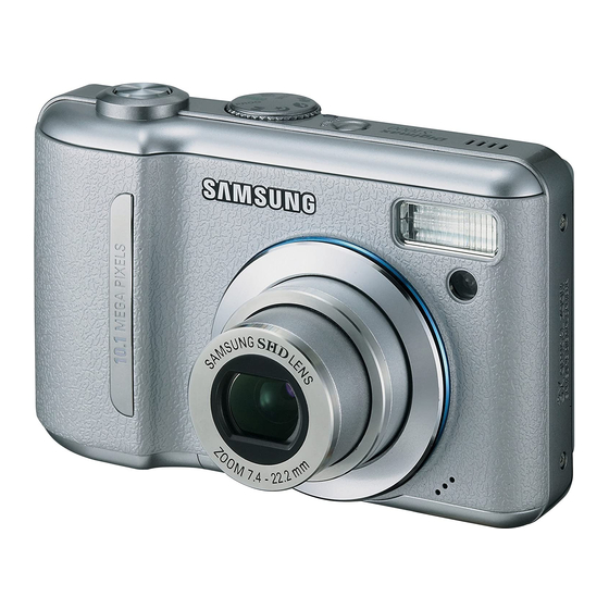
Ⅰ. SPECIFICATION 1. CAMERA SPECIFICATION ■ Image Sensor - Type : 1/1.8" CCD - Effective Pixel : Approx. 10.1 Mega-pixel - Total Pixel : Approx. 10.3 Mega-pixel ■ Lens - Focal Length : SHD Lens f = 7.4 ~ 22.2mm (35mm film equivalent : 35 ~ 105mm) - F No. - Page 5 Fine 1116 Normal 1041 1302 * These figures are measured under Samsung’ s standard conditions and may vary depending on shooting conditions and camera settings. ■ Image Play - Type : Single image, Thumbnails, Slide show, Movie Clip - Editing : Trimming, Resizing, Rotate, Effect ■...
-
Page 6: System Requirements
Ⅰ. SPECIFICATION 2. System Requirements For Windows For Macintosh PC with processor better than Pentium II 450MHz Power Mac G3 or later (Pentium 700MHz recommended)) Windows 98 / 98SE / 2000 / ME / XP Mac OS 9.2 ~ 10.3 Minimum 64MB RAM Minimum 64MB RAM 200MB of available hard disk space... - Page 7 Ⅰ. SPECIFICATION Description Icons Recording mode Battery Aperture Value / Shutter Speed F2.8, 1/30 Continuous shot Flash / Without Sound Self-timer Macro Metering Card inserted indicator Auto focus frame Camera shake warning Date / Time 2006/07/01 01:00 PM Exposure compensation White Balance Sharpness Image quality / Frame rate...
- Page 8 Ⅰ. SPECIFICATION ■ Play mode ⑫ ① ② ⑪ ISO : 80 ③ ⑩ Av : F 2.8 ④ ⑨ Tv : 1/30 ⑤ Flash : On ⑧ ⑦ 3648 x 2736 ⑥ 2006/07/10 Description Icons Play mode icon Battery Voice Memo Protect DPOF...
-
Page 9: Connection Diagram
Ⅰ. SPECIFICATION 4. CONNECTION DIAGRAM... -
Page 10: Identification Of Features
Ⅰ. SPECIFICATION 5. IDENTIFICATION OF FEATURES Front & Top Mode dial Power button Shutter button Speaker Flash Self-timer lamp / Strap eyelet Auto focus lamp Lens / Lens cover Microphone Back & Bottom Camera status lamp Zoom W button (Thumbnail) Zoom T button (Digital zoom) E (Effects) button LCD monitor... - Page 11 Ⅰ. SPECIFICATION Bottom / 5-function button Voice memo / Voice Recording / Up button Menu / OK button Flash / Self-timer / Left button Right button Battery chamber cover Macro / Down button Play & Pause button Memory card slot Battery chamber Cradle (Optional) ●...
-
Page 12: Ⅱ Ⅱ . Installation & Faq
Ⅱ. INSTALLATION & FAQ 1. The auto run frame will display. Click the [Install] menu in the Auto run frame. 2. Install the camera driver, DirectX, Xvid and Digimax Master by selecting a button shown on the monitor. If an upper version of DirectX was installed on your computer, DirectX may not be installed. - Page 13 Ⅱ. INSTALLATION & FAQ...
- Page 14 Ⅱ. INSTALLATION & FAQ...
- Page 15 Ⅱ. INSTALLATION & FAQ 3. After restarting the computer, connect the PC to the camera with the USB cable. 4. Turn the camera power on. The [Found New Hardware Wizard] will open and the computer will recognise the camera. ※ If your OS is Windows XP, an image viewer program will open.
-
Page 16: Main Assembly
Ⅲ. EXPLODED VIEW AND PART LIST 1. MAIN ASSEMBLY... -
Page 17: Body Assembly
Ⅲ. EXPLODED VIEW AND PART LIST 2. BODY ASSEMBLY 2-27 2-28 2-28 2-27 2-22 2-24 2-16 2-16 2-23 2-15 2-21 2-25 2-26 2-16... -
Page 18: Barrel Assembly
Ⅲ. EXPLODED VIEW AND PART LIST 3. BARREL ASSEMBLY 3-50 3-51 3-11 3-49 3-10 3-40 3-28 3-27 3-26 3-22 3-30 3-29 3-23 3-30 3-30 3-17 3-16 3-24 3-14 3-19 3-18 3-25 3-15 3-21 3-13 3-20 3-12 3-54 3-35 3-32 3-46 3-44 3-34 3-31... -
Page 19: Barrier Assembly
Ⅲ. EXPLODED VIEW AND PART LIST 4. BARRIER ASSEMBLY... -
Page 20: Front Cover Assembly
Ⅲ. EXPLODED VIEW AND PART LIST 5. FRONT COVER ASSEMBLY 5-11 5-12 5-11 5-13... -
Page 21: Middle Cover Assembly
Ⅲ. EXPLODED VIEW AND PART LIST 6. MIDDLE COVER ASSEMBLY ● 6-11 6-10 6-14 6-15... -
Page 22: Back Cover Assembly
Ⅲ. EXPLODED VIEW AND PART LIST 7. BACK COVER ASSEMBLY... -
Page 23: Packing Item
Ⅲ. EXPLODED VIEW AND PART LIST 8. PACKING ITEM 8-19 8-14 8-15 8-17 8-18 8-21 8-16 8-20 8-10 8-11 8-12 8-13... - Page 24 Fig.No Old Code New Code Parts Name Q'ty Supply Remark 1.MAIN ASSEMBLY Q9001109501A AD97-13769A BATTERY COVER_ASSY Q6003042701A 6003-001671 SCREW Q6003048801A 6003-001676 SCREW Q6003042701A 6003-001671 SCREW SILVER Q9761175012 6003-001695 SCREW BLACK Q0961900301A 6003-001630 SCREW Q9761173007A DNA SCREW 2.BODY ASSEMBLY Q7211083806B AD81-03446A BATTERY_CHAMBER Q7011055603A AD67-00621A BATTERY_CONTACT...
- Page 25 2-24 Q7014004801A AD67-00634A REFLECTOR-D3(7M3X) 2-25 Q0611003301A AD47-00013A XE TUBE 2-26 Q7214088801A AD67-00752A FRESNEL LENS 2-27 Q0961900301A 6003-001630 SCREW 2-28 Q9761145007 SCREW 2-29 Q0704013301A AD81-00215A 2-30 Q9008110101A AD92-00308A MAIN_PCB_ASSY 2-31 Q7011058601A AD81-02814A LCD_FRAME 2-32 Q7409219701A AD81-05114A LCD_PROTECT_TAPE 3.BARREL ASSEMBLY Q7012080802A AD61-03230A AF CLIP HOLDER Q7012088601A AD61-03596A AF CLIP...
- Page 26 3-26 Q7212190902A DNA LENS BASE 3-27 Q3107002401A AD31-00067A ZOOM MOTOR 3-28 Q7212189601A AD66-00504A ZOOM MOTOR GEAR 3-29 Q9611142007 6001-002171 SCREW 3-30 Q0961900301A 6003-001630 SCREW 3-31 Q7012086601A AD64-01752A CAM DECORATION RING 3-32 Q7212190602A AD67-00664A CAM BARREL 3-33 Q7212190401A AD81-03655A GUIDE PLATE 3-34 Q9002145101A AD97-13443A OUTER GUIDE BARREL 3-35 Q7212190701A AD67-00666A...
- Page 27 5-10 Q7211059102A AD61-03371A TRIPOD_CONNECTOR 5-11 Q6003027501A 6003-001666 SC_1430 5-12 Q7017052401A AD61-03293A SAMSUNG_LOGO 5-13 Q6003042701A 6003-001671 63_SC_1750 6.MIDDLE COVER ASSEMBLY Q9007274101A AD97-14417A MIDDLE_COVER_ASSY-DIGIMAX S1000 Q9007274101B AD97-14418A MIDDLE_COVER_ASSY-KENOX S1000 Q7217372807B DNA MIDDLE_COVER-DIGIMAX S1000 Q7217372807C DNA MIDDLE_COVER-KENOX S1000 Q6107059701A 6107-001413 RELEASE_SPRING Q7217373802A AD64-01859A...
- Page 28 6-12 Q3001000601A 3001-002315 SPEAKER 6-13 Q7409225102A AD63-01976A SPEAKER TAPE 6-14 Q0961900301B DNA SCREW 6-15 Q9761173007A DNA SCREW 6-16 Q7217373903A AD61-03464A STRAP_INNER_HOLDER 6-17 Q7217369001B AD64-01848A POWERBUTTON 6-18 Q7217368802B DNA MODEDIAL 7.BACK COVER ASSEMBLY Q9007274301A AD97-14424A BACK_COVER_ASSY SILVER Q9007274301B AD97-14425A BACK_COVER_ASSY Q7217373702B AD64-01858A AF LED LAMP Q7217373402A AD81-04531A NAVI BUTTON...
- Page 29 Q6806018701A DNA Q_GUIDE_Digimax_S1000_DUT Q6806018801A DNA Q_GUIDE_Digimax_S1000_POR Q6806018901A DNA Q_GUIDE_Digimax_S1000_SWE Q6806019001A DNA Q_GUIDE_Digimax_S1000_DEN Q6806019101A DNA Q_GUIDE_Digimax_S1000_FIN Q6806019201A DNA Q_GUIDE_Digimax_S1000_RUS Q6806019301A DNA Q_GUIDE_Digimax_S1000_CHI(S) Q6806019401A DNA Q_GUIDE_Digimax_S1000_TK Q6806019501A DNA Q_GUIDE_Digimax_S1000_IND Q6806019601A DNA Q_GUIDE_Digimax_S1000_ARA Q6806026601A DNA Q_GUIDE_Digimax_S1000_THA Q6806017801A DNA Q/GUIDE_KENOX_S1000_KOR Q6806017901A AD81-01612A U/MANUAL_KENOX_S1000_KOR Q6806020101A AD81-01613A U_MANUAL_Digimax_S1000_ENG Q6806020201A AD81-01614A U_MANUAL_Digimax_S1000_GER...
- Page 30 MIC LABEL_KENOX S1000(MADE IN KOREA) Q7409250101A DNA MIC LABEL_KENOX S1000(MADE IN CHINA) 8-20 Q7409249601A DNA FCC LABEL_Digimax S1000_EXP(MADE IN KOREA) Q7409249701A AD81-05206A FCC LABEL_Digimax S1000_EXP(MADE IN CHINA) Q7409249901A AD68-02545A FCC LABEL_Digimax S1000_EXP(MADE BY SAMSUNG) 8-21 Q7409250201A AD81-05207A PRODUCT STICKER_KENOX S1000...
-
Page 31: Digital Camera Service
Ⅳ. ADJUSTMENT 1. Digital camera service To take a digital camera service (Repair, Tuning and Checking), the following equipments have to be arranged. The sequences for the camera service are as shown. Receiving the camera 1. Receiving the camera When receiving a camera, check whether the accessories are Checking the camera included or not and ask the customer exact problems. - Page 32 Ⅳ. ADJUSTMENT 1) Equipments for checking and inspection To check and inspect the camera malfunction, the following equipments have to be arranged. ⑥ ④ ↓ ③ ② ⑤ → ① ⑦ ⑪ ⑧ ⑨ → ← ⑩ Device Description PC for inspection - Installing a digital camera driver or Checking the removable device - Checking the file transference(upload and download) - Playing back the still image or movie clip...
- Page 33 Ⅳ. ADJUSTMENT 2) Equipments for camera repair To repair the camera, the following equipments have to be arranged. ⑧ ⑩ → ⑬ ④ ⑫ ⑨ ③ ⑥ ⑦ ② ① ⑪ → ⑤ Device Description A set of tools Pincette/ Screwdriver/ Discharger etc. Cleaning paper For cleaning camera lens and camera parts Detergent container...
- Page 34 Ⅳ. ADJUSTMENT 3) Equipments for camera tuning To tune the camera, the following equipments have to be arranged. ⑤ ② ④ ① ⑥ ③ Device Description AE TESTER For tuning AE and STROBE AWB LIGHT For checking and tuning AWB SOURCE BOX COLOR chart For checking AWB and color of images...
- Page 35 - When the cable is inserted, check whether the images play back on the external monitor. Turn on the camera. - Check whether the green LED is blinking, SAMSUNG LOGO is on and the start-up sound sounds. - Check the “L” and “FINE” icon on the LCD monitor.
- Page 36 Ⅳ. ADJUSTMENT Checking item Check point - Check whether the icon and counter are displayed on the LCD MANUAL focus. monitor. Take a movie clip with TELE zoom - Check whether the recording time is displayed and there are a during 10 seconds.
-
Page 37: Firmware
Ⅳ. ADJUSTMENT 2. FIRMWARE 1) Reseting Camera 1. Turn on the Camera 2. Press the Up button twice and the Voice recording mode will be selected. 3. Press and hold the Up button and Shutter button and then press the Power button again. 4. - Page 38 Ⅳ. ADJUSTMENT 2) Checking Firmware 1. Remove the memory card from the camera. 2. Turn on the camera. 3. Press the Up button twice to select the Voice Recording mode. 4. Press the 5 function button as following order. (Left 5.
- Page 39 Ⅳ. ADJUSTMENT 3) Upgrading Firmware 1. Insert the SD card that has the firmware. ※Updating the firmware will delete all data in the SD card. Be sure to download all data to your PC before updating the firmware. The firmware file name must be " STS2_103.ELF " and use the AC adapter or fully charged battery.. 2.
- Page 40 Ⅳ. ADJUSTMENT 5. Press the 5 function button as following order. 4. Press the Up button twice to select the Voice (Left button Right button Up button +/- button) Recording mode. 6. ‘NOW UPGRADING!' message will display and then the firmware will be upgraded. 7.
- Page 41 Ⅳ. ADJUSTMENT 4) Full Version of Firmware1 How to use the FULL version of Firmware1 When the camera is not turned on, do the Full version upgrade. ▷ Camera Status : When turning on the camera, the power consumption (Checking the POWER SUPPLY) is 200- 300mA and the camera can ’t be operated.
- Page 42 Ⅳ. ADJUSTMENT 5) Full Version of Firmware2 How to use the FULL firmware2 Depending on the camera status, do the full version upgrade. ▷ Reference : - Delete all data in the memory card and upgrade with this firmware. - When using the full version upgrade, back up the script file as the files will be deleted by the upgrade. - If the full version upgrade is done by the following way, the script files are saved on the SD card.
- Page 43 Ⅳ. ADJUSTMENT 3. Turn on the Camera. 4. Press the Up button twice to select the Voice Recording mode. 5. Press the 5 function button as following order. (Left button → Right button → Down button → +/- button)
- Page 44 Ⅳ. ADJUSTMENT 6. ‘NOW UPGRADING!' message will display and then the firmware will be upgraded. - When the full version firmware is upgrading, the script files are saved on the SD card automatically and if LSCLUT0.BIN, DefectivePixel0.bin, DefectivePixel1.bin files are in the SD card, the back up is done. 7.
-
Page 45: Basic Information Of Adjustment
Ⅳ. ADJUSTMENT 3. Basic Information of Adjustment 1. To adjust the camera after changing the electronic parts, see the below table. MAIN POWER BARREL PROCESS ASSY ASSY CODE FIRMWARE UPGRADE ● ● PUNT ADJ ● ● ● ● ● ● CCD DEFECT CELL ●... - Page 46 Ⅳ. ADJUSTMENT < Description of TXT file > PROGRAM Codes of program <1>PROCESS CODE ; Insert the PROCESS CODE that you want to adjust <2>65535 ; 65535..-->..DEFAULT <3>PROCESS CODE ; Insert the PROCESS CODE that you want to adjust <4>0 OR 1 ; Insert 1 to write adjusted code to the EEPROM <5>0 OR 1 ;...
- Page 47 Ⅳ. ADJUSTMENT 1) OB SETTING After changing the MAIN PCB, adjust the black color.. <How to adjust> a...Download program and save it to SD memory card. b... Insert the SD memory card that has the program file and turn on the camera. c...
- Page 48 Ⅳ. ADJUSTMENT < Description of TXT file > When making or modifying the program, see the following program codes. When modify the program, use the Memo Pad of Windows and save it as “STS2_103ADJ.txt”. PROGRAM Description of the codes <1>PROCESS CODE ; <1>18;...
- Page 49 Ⅳ. ADJUSTMENT 2) LENS SHADING This menu adjust the brightness gaps between center of the lens and around the lens. Required Equipment : AE TESTER(LV: 8.2) <How to adjust> a...Prepare AE TESTER can be test up to LV8.2. b...Download program file and save it to SD memory card. c...
- Page 50 Ⅳ. ADJUSTMENT e... Turn on the camera. f...<Figure 2-1> will be displayed on the TFT LCD and the adjustment will be done automatically. <Figure 2-1> e...After completing the upgrade, the camera is turned off automatically. ※ If the adjustment is incomplete, <Figure 2-2> will display. In this case, re-try the adjustment process.
- Page 51 Ⅳ. ADJUSTMENT 3) B/T LEVEL ADJ After changing the MAIN PCB, adjust WARNING LEVEL and LOCK LEVEL. Required Equipment : POWER SUPPLY(2.71V) <How to adjust> a...Prepare the POWER..SUPPLY. b...Connect the camera to the POWER..SUPPLY. c...Set the voltage to 2.71V. d...Downloading the program file and save it to SD memory card. e...Insert the SD memory card and turn on the camera.
- Page 52 Ⅳ. ADJUSTMENT < Description of TXT file > When making or modifying the program, see the following program codes. When modify the program, use the Memo Pad of Windows and save it as “STS2_103ADJ.txt”. Description of codes PROGRAM <1>5; <1>PROCESS CODE ; <2>65535;...
- Page 53 Ⅳ. ADJUSTMENT 4) BACK LASH ADJ After changing the MAIN PCB, BARREL and CCD, adjust the BACK LASH. <How to adjust> a...Download the Program file and save it to SD memory card. b...Insert the SD memory card that has program file and turn on the camera. c...
- Page 54 Ⅳ. ADJUSTMENT < Description of TXT file > When making or modifying the program, see the following program codes. When modify the program, use the Memo Pad of Windows and save it as “STS2_103ADJ.txt”. PROGRAM Description of codes <1>PROCESS CODE ; <1>9;...
- Page 55 Ⅳ. ADJUSTMENT 5) SHUTTER CLOSE TIME ADJ After changing the MAIN PCB, BARREL and CCD, adjust the SHUTTER CLOSE TIME. Required Equipment: AE TESTER(LV 15.8±0.1.) < How to adjust > a...Prepare AE TESTER that can be test up to LV 15.8±0.1. b...Attach the camera to the AE TESTER.
- Page 56 Ⅳ. ADJUSTMENT < Description of TXT file > When making or modifying the program, see the following program codes. When modify the program, use the Memo Pad of Windows and save it as :STS2_103ADJ.txt”. PROGRAM Description of codes <1>PROCESS CODE ; <1>7;...
- Page 57 Ⅳ. ADJUSTMENT 6) FLASH ADJ After changing the MAIN PCB and SUB PCB, adjust the FLASH. Required Equipment : Dark room, Gray chart (36% reflect paper), Tripod < How to adjust > a...Arrange a 36% reflect chart in a darkroom.. b...
- Page 58 Ⅳ. ADJUSTMENT < Description of TXT file > When making or modifying the program, see the following program codes. When modify the program, use the Memo Pad of Windows and save it as “STS2_103ADJ.txt”. Description of codes PROGRAM <1>13; <1>PROCESS CODE ; <2>65535;...
- Page 59 Ⅳ. ADJUSTMENT 7) FOCUS ADJ After changing the MAIN PCB and BARREL, adjust the PUNT. Required Equipment : Chart for FOCUS adjustment,Tripod < How to adjust > a... Arrange a chart for adjust the FOCUS. b... Attach the camera to the tripod. c...
- Page 60 Ⅳ. ADJUSTMENT < Description of TXT file > When making or modifying the program, see the following program codes. When modify the program, use the Memo Pad of Windows and save it as “STS2_103ADJ.txt”. D D e e s s c c r r i i p p t t i i o o n n o o f f c c o o d d e e s s PROGRAM <1>2;...
- Page 61 Ⅳ. ADJUSTMENT 8) BURNING TEST BURNING TEST : After changing the MAIN PCB and parts, check whether all of the camera functions work correctly. CCD DEFECT CELL : After changing the MAIN PCB and CCD, adjust the DEFECT CELL of CCD. <...
- Page 62 Ⅳ. ADJUSTMENT < Codes of program > Function code code Function DELETE..ALL MACRO..SHOOTING LCD..ON CONTINUOUS..SHOOTING(2) WIDE SELF..TIMER..(10..sec.) TELE PLAY..MODE NOT..USE SLIDE..SHOW FLASH..ONSHOOTING MOVIE..CLIP..RECORD FLASH..OFF..SHOOTING MOVIE..PLAY NORMAL..SHOOTING b... Save the program on the SD card. c... Insert the SD memory card that has the program file and turn on the camera. d...
- Page 63 Ⅳ. ADJUSTMENT 9) EEPROM READ To read the data of EEPROM, refer to the below codes. <How to read> a...Insert the codes (from START ADDRESS 0 to END ADDRESS 500) and save the program in the SD card. b... Insert the SD memory card that has the program file and turn on the camera. c...
- Page 64 Ⅳ. ADJUSTMENT 10) EEPROM WRITE If you want to write the DATA of EEPROM, do as follows. <How to write> a...Insert the codes (from 0 to 540) and save the program in the SD card. b... Insert the SD card to the camera and turn on the camera. c...
-
Page 65: Parts Arrangement For Each Pcb Ass'y
Ⅴ. PATTERN DIAGRAM 1. PARTS ARRANGEMENT FOR EACH PCB ASS’Y 1) MAIN_TOP... -
Page 66: Main_Bottom
Ⅴ. PATTERN DIAGRAM 2) MAIN_BOTTOM... -
Page 67: Mode
Ⅴ. PATTERN DIAGRAM 3) MODE... - Page 68 Ⅴ. PATTERN DIAGRAM 4) CCD...
- Page 69 Ⅴ. PATTERN DIAGRAM 5) FLASH...
- Page 70 Ⅵ. CIRCUIT DIAGRAM Ⅵ. CIRCUIT DIAGRAM 1) MAIN...
- Page 71 Ⅵ. CIRCUIT DIAGRAM 2) MAIN_BLOCK...
- Page 72 Ⅵ. CIRCUIT DIAGRAM 3) MAIN_FEP...
- Page 73 Ⅵ. CIRCUIT DIAGRAM 4) MAIN_DDR & MEMORY...
- Page 74 Ⅵ. CIRCUIT DIAGRAM 5) MAIN_I/O&LCD...
- Page 75 Ⅵ. CIRCUIT DIAGRAM 6) MAIN_KEY...
- Page 76 Ⅵ. CIRCUIT DIAGRAM 7) MAIN_LENS(MOTOR)
- Page 77 Ⅵ. CIRCUIT DIAGRAM 8) MAIN_POWER...
- Page 78 Ⅵ. CIRCUIT DIAGRAM 9) MAIN_STROBO...
- Page 79 Ⅵ. CIRCUIT DIAGRAM 10) CCD...
- Page 80 Ⅵ. CIRCUIT DIAGRAM 11) MODE...
- Page 81 Ⅵ. CIRCUIT DIAGRAM 12) STROBO...
- Page 82 Ⅶ. SERVICE INFORMATION 1. Cautions of Disassembly and Assembly ■ Caution 1... Do the disassembling and assembling camera where the blocking static electricity mat is on the table. 2... When handling the major PCBs of camera, please wearing the band which cuts off the electric current on the wrist.
- Page 83 Ⅷ. SERVICE INFORMATION ■ Disassembly Camera 1. Remove 2 screws. 2. Remove 2 screws. 3. Remove 3 screws.
- Page 84 Ⅷ. SERVICE INFORMATION 4. Disassemble the BACK COVER. ■ Disassembling the LCD ASSY 5. Lift up the LCD and move to the direction as 6. Remove 3 screws. shown.
- Page 85 Ⅷ. SERVICE INFORMATION 7. Disassemble the LCD ASSY guide panel. 8. Remove 2 wired (Black, Gray) and disconnect the PCB from the connector. 9. Disassemble the LCD ASSY.
- Page 86 Ⅷ. SERVICE INFORMATION 10. Disconnect the PCB from the connector. 11. Disassemble the FRONT COVER.
- Page 87 Ⅷ. SERVICE INFORMATION ■ Disassembling the MAIN PCB ASSY 12. No.1 : Before removing the PCB soldering, discharge the main condenser. No.2 : Remove the 2 soldering of battery contact. No.3 : Disassemble the connector. 13. Remove 2 screws. 14. Disconnect the CCD PCB from the connector.
- Page 88 Ⅷ. SERVICE INFORMATION 15. Disassemble the MAIN PCB. 16. Remove 3 screws. 17. Disassemble the Barrel ASSY.
- Page 89 Ⅶ. SERVICE INFORMATION 18. Remove 2 screws. 19. Disassemble the STROBE PCB.
- Page 90 Ⅷ. SERVICE INFORMATION ■ Assemble Camera 1. Attach the STROBE PCB. 2. Assemble 2 screws. 3. Attach the Barrel ASSY.
- Page 91 Ⅷ. SERVICE INFORMATION 4. Assemble 3 screws. 5. Attach the MAIN PCB. 6. Connect the CCD PCB to the connector.
- Page 92 Ⅷ. SERVICE INFORMATION 7. Assemble 2 screws. 8. No. 1 : solder the PCB, No. 2 : Solder 2 points of battery contacts, No.3 : Connect the PCB to the connector. 9. Assemble the Microphone first and attach the FRONT COVER.
- Page 93 Ⅷ. SERVICE INFORMATION 10. Connect the PCB to the connector and solder the 2 wires (Red, Black) of the Microphone. 11. Assemble the LCD ASSY. 12. Solder 2 wires (Black, Gray) and connect the PCB to the connector. 13. Attach the LCD ASSY guide panel.
- Page 94 Ⅷ. SERVICE INFORMATION 15. Fix the LCD ASSY as shown. 14. Assemble 3 screws. 17. Assemble 3 screws. 16. Attach the BACK COVER. 18. Assemble 2 screws. 19. Assemble 2 screws.
- Page 95 Ⅷ. SERVICE INFORMATION ■ Disassemble Barrel 1. Remove soldering and 3 screws. h X 3 After disassembling the Lens base 2. To disassemble the Barrel, remove the screw that holds the F PCB. d X 1...
- Page 96 Ⅶ. SERVICE INFORMATION 3. Disassemble the Outer Cam Barrel and Outer Guide Barrel. 4. Disassemble the Outer Cam Barrel and Outer Guide Barrel. To disassemble the Outer Guide Barrel, rotate it to the guide of Outer Cam Barrel. 5.Disassemble the Cam Barrel and Guide Plate.
- Page 97 Ⅶ. SERVICE INFORMATION 6. To disassemble the Guide Plate from the Cam Barrel, press the 3 points of the Guide Plate inside and remove it. 7. Disassemble the 2nd Lens Ass'y and Shutter Ass'y. Take care of the double glue tape when 8.
- Page 98 Ⅶ. SERVICE INFORMATION 9. Disassemble the Shutter Ass'y. After disassembling the Shutter Ass’ y...
- Page 99 Ⅶ. SERVICE INFORMATION ■ Assemble Barrel 1. Taking care of the F PCB, assemble the Shutter Ass'y. In this case, assemble the F PCB to 2nd Lens Ass'y firmly.
- Page 100 Ⅶ. SERVICE INFORMATION 2. Assemble a screw and attach the Shield Tape. 3. Taking care of the direction of the PCB Guide, assemble them. Attach the F PCB to the F PCB Guide firmly.
- Page 101 Ⅶ. SERVICE INFORMATION 4. Assemble the 2nd Lens Ass'y and Zoom Ring Ass'y. After assembling them 5. Assemble the Cam Barrel and Guide Plate. To assemble them press the Guide Plate as shown. You can hear ‘Click’ sound when they are assembled correctly.
- Page 102 Ⅶ. SERVICE INFORMATION 6. Match the Boss part of the Outer Guide Barrel and Guide part of the Outer Guide Barrel. 7. Assemble the zoom Ring + 2nd Lens Ass'y and Cam Barrel + Guide Plate. Before assembling them, rotate the Guide Plate until the groove of the Cam Barrel is shown. 8.
- Page 103 Ⅶ. SERVICE INFORMATION 9. Assemble the Outer Cam Barrel and Outer Guide Barrel. When assembling them, take care of the position of the screw hole of Outer Cam Barrel and reflector of Outer Guide Barre 10. After assembling them, assemble screws. 11.
- Page 104 Ⅶ. SERVICE INFORMATION 12. Assemble 3 screws and solder the Shutter F PCB. h X 3...
Need help?
Do you have a question about the Digimax S1000 and is the answer not in the manual?
Questions and answers