Table of Contents
Advertisement
Quick Links
Advertisement
Table of Contents
Troubleshooting

Related Manuals for Manitowoc Flav’R-Pic FRP-250, Flav’R-Pic FRP-250SCI


Summary of Contents for Manitowoc Flav’R-Pic FRP-250, Flav’R-Pic FRP-250SCI
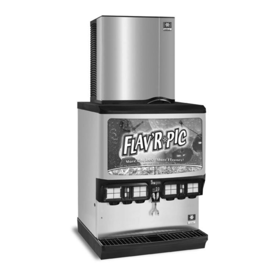
- Page 1 Flav’R-Pic Series Selectable Ice / Beverage Dispensers Installation, Use & Care Manual This manual is updated as new information and models are released. Visit our website for the latest manual. www.manitowocfsg.com Leader in Ice & Beverage Dispensers Part Number 020003315 1/11...
- Page 2 Safety Notices Read These Before Proceeding: As you work on Manitowoc equipment, be sure to pay close attention to the safety notices in this manual. ! Caution Disregarding the notices may lead to serious injury and/ Proper installation, care and maintenance are or damage to the equipment.
-
Page 3: Table Of Contents
Accessories............® Baffle for Manitowoc Ice Machine ....... - Page 4 Grounding Instructions ..........Pump Deck Wiring .
- Page 5 Auto Bag Selectors ......... . . FRP-250 Non-Adjustable Agitation Timer .
- Page 6 Table of Contents Sanitizing............Beverage System Cleaning .
-
Page 7: Read This Manual
Unit Inspection BAFFLE FOR MANITOWOC® ICE MACHINE Thoroughly inspect the unit upon delivery. Immediately When installing a Manitowoc Ice Machine on a report any damage that occurred during transportation to dispenser, a baffle kit is required for proper installation. the delivery carrier. Request a written inspection report... -
Page 8: Legs
General Information Section 1 LEGS Warranty Information Legs are optional equipment with most MBE dispensers. Consult your local MBE Distributor for terms and Standard legs are 4" (10.2 cm) tall stainless steel legs. If conditions of your warranty. Your warranty specifically an ice machine is installed on top of the dispenser, legs excludes all beverage valve brixing, general must not be installed. -
Page 9: General
Important These instructions are provided to assist the qualified Failure to follow these installation guidelines may installer. Contact your Manitowoc Beverage Equipment affect warranty coverage. Service Agent or call Manitowoc Beverage Equipment for information regarding start-up services. Dimensions FRP-250 250* 39.81"... -
Page 10: Frp-250 Footprint
Installation Instructions Section 2 FRP-250 Footprint Maximum Area for Cutout Minimum Area for Cutout Maximum Minimum Flav’R-Pic 250* 26.00" 17.81" 4.00" 24.00" (66.0 cm) (45.2 cm) (20.30 cm) (61.00 cm) ! Caution Cutting the countertop may decrease its strength. Counter must be braced to support the dispenser countertop weight plus ice storage capacity and weight of icemaker, if applicable. -
Page 11: Location
Section 2 Installation Instructions Location Location Requirements for Top Mounted Ice Machine Installations The location selected for the beverage dispenser must meet the following criteria. If any of these criteria are not Location — Avoid placing the dispenser and/or ice met, select another location. -
Page 12: Pre-Installation Checklist
Installation Instructions Section 2 Pre-installation Checklist When installing any system, first make sure the major components are available. Generally the major components necessary for an installation are: PRE-MIX SYSTEM POST MIX SYSTEM regulator set regulator set Product connectors for Figal tank Beverage dispenser Gas connectors for Figal tank Beverage tubing... -
Page 13: Double Check:
Section 2 Installation Instructions DOUBLE CHECK: ADDITIONAL CHECKS FOR TOP MOUNTED ICE MACHINE INSTALLATIONS Do you have enough space to install the Location — Avoid placing the dispenser and/or dispenser or a dispenser and top mounted ice ice machine near heat sources such as machine? radiators, ovens, refrigeration equipment and direct sunlight. -
Page 14: Assembly
6.32" 7. Replace the front panels. (16.0 cm) Ref. 7.22" (18.3 cm) Baffle, Manitowoc Ice Ref. Machine "Q" Series Ice Machine Backing Plate to Be Inserted Into Side Pocket of... -
Page 15: Grounding Instructions
Section 2 Installation Instructions Electrical Grounding Instructions GENERAL Warning Risk of electrical shock. Connect to a properly Warning grounded outlet only. All wiring must conform to local, state and national codes. This appliance must be grounded. In the event of MINIMUM CIRCUIT AMPACITY malfunction or breakdown, grounding provides a path of least resistance for electric current to reduce the risk of... -
Page 16: Pump Deck Wiring
Installation Instructions Section 2 PUMP DECK WIRING The supply cord is equipped with a three prong 5-15P. Warning When a Ground Fault Circuit Interrupter (GFCI) is When using electric appliances, basic precautions required by code, a breaker type protector must be should always be followed, including the following: used. -
Page 17: Water Supply
Section 2 Installation Instructions Water Supply DIAGRAM LOCATION RECOMMENDED PLUMBING The plumbing diagram is printed on a white vinyl label, normally located above the inlet tubes for syrup and water. The plumbing diagram label can be accessed by removing the splash panel of the dispenser. The plumbing diagram label explains which inlet coldplate fittings supply which dispenser valves and water manifolds. -
Page 18: Frp-250 Plumbing Diagram
Installation Instructions Section 2 FRP-250 PLUMBING DIAGRAM C1 / C2/ NC2 C3 / C4/ NC3 S1-S8 / F1-F4 S9-S16 / F5-F8 CONTROL BOARD CONTROL BOARD LEFT SIDE RIGHT SIDE NCS3 S15 S14 NCS2 LEFT BEVERAGE VALVES RIGHT BEVERAGE VALVES C2 / NC2 C3 / NC3 LEFT TOUCHPADS RIGHT TOUCHPADS... -
Page 19: Co2 System
Section 2 Installation Instructions System 3. Depending on drain location route the tubing through the tubing bundle cutout or out the back of ROUTING INTERNAL CARB TANK PURGE TUBE the dispenser. Some models are equipped with an internal carbonation tank.These models require that the purge/pressure relief Rear of Unit tubing be routed to a drain. -
Page 20: Step By Step Installation
Installation Instructions Section 2 Step by Step Installation 7. Purge air from the carbonator tank. Lift the pressure relief valve tab on the carbonator tank until water GENERAL comes out of the relief valve. Flav’R-Pic and Selectable Ice Series dispensers have a 8. -
Page 21: Brixing Procedure
Section 2 Installation Instructions BRIXING PROCEDURE LEFT BOARD RIGHT BOARD If the merchandiser and splash panel are on the front of C1 - VALVE 8 C3 - VALVE 4 the unit, remove them. Merchandiser removal will give C2 - VALVE 11 C4 - VALVE 1 NC2 - VALVE 11 NC3 - VALVE 4... -
Page 22: General Brixing Process
Installation Instructions Section 2 2. To brix carbonated or non-carbonated water for a dispense point leave the nozzle in place and hold the brix cup with the water side of the cup under the LEFT SIDE RIGHT SIDE nozzle area. Non-Carbonated water is only available CONTROL BOARD CONTROL BOARD Valve Controls - C1, C2, NC2... -
Page 23: Nozzle 1 (N1) Water And Syrup Brixing
Section 2 Installation Instructions NOZZLE 1 (N1) WATER AND SYRUP BRIXING the water side of the cup under N3 (Nozzle 3), and press the F3 (Flavor Shot 3) button. Water will 1. With the left control board set to brix mode and dispense for a fixed duration. -
Page 24: Nozzle 5 (N5) Water And Syrup Brixing
Installation Instructions Section 2 5. For syrup brixing place the brix cup with the syrup side 7. Move to another nozzle or if you are finished brixing return the control board to the dispense mode by of the cup under the N4 (Nozzle 4) and press the touch pressing the program button and holding for 3 seconds pad area for S9 (Syrup 9), S10, S11, or S12 and the or until the LED displays 0. -
Page 25: Operation
Section 3 Operation Section 3 Operation General System Overview Dispenser Carbonator Tank Carbonate, Non-carbonate Beverage Manifold Counter top BIB Syrup Pump Syrup Tap Water Primary Regulator Bag-in-box Syrup Carton 1800 Tap Water BIB Syrup Pump Syrup Bag-in-box Syrup Carton Cylinder Typical Flav’R-Pic Series Internal Carbonation Beverage Dispensing System Part Number 020003315 1/11... -
Page 26: Component Identification
Operation Section 3 Merchandiser Selectable Ice Touch Pad Lower Merchandiser Nozzles & Beverage Selection Touch Pads Key Switch Ice Chute Nozzles ADA Touch Pads (on units with this feature) ADA Touch Pads Drainpan Grid (on units with this feature) Splash Panel Drainpan Component Identification Sequence of Operation... -
Page 27: Rocking Chute Ice Dispensing
Section 3 Operation ROCKING CHUTE ICE DISPENSING Operation On units without the selectable ice option, as the Carbon Dioxide (CO ) leaves the storage tank and customer presses the rocking chute, the arm at the top arrives at the carbonator tank through the gas inlet. left rear of the chute pushes upward on the door lock. -
Page 28: Racking
Operation Section 3 1. Incoming tap water - should be at a minimum B-I-B dynamic pressure of 40 psi and maximum static The Bag-In-Box system refers to a plastic disposable bag. pressure of 70 psi. The B-I-B normally contains 5 gallons of syrup, however 2. -
Page 29: Control Box Label
Section 3 Operation CONTROL BOX LABEL Operation Checks and Adjustments FRP-250 (NON-ICE CRUSHING UNIT) ICE DELIVERY SWITCH ADJUSTMENT To properly adjust the switch, first unplug the power cord to the unit then remove the merchandiser. This will give you access to the ice delivery switch located on the left side of the rocking chute. -
Page 30: External Brix Mode
Operation Section 3 EXTERNAL BRIX MODE 4. In this mode you can now check the brix for any water or syrup valve that corresponds to the board. Use the How to Check FRP Brix Externally illustration in Installation/Brixing or the Control board, If your FRP-250 has a control board with the external brix Valve, Touch Pad Matrix to identify the valves and which check ability you will be able to put the unit into brix mode by... -
Page 31: Carb/Non-Carb & Flavor Shot Duration Settings
Section 3 Operation PROGRAM MODE 1 3. To set a carbonated drink for N3 (Nozzle 3) touch one of the following touch pads; S5, S6, S7, or S8 Carb/Non-Carb & Flavor Shot Duration Settings until the LEDs around the touch pad are constant. 4. -
Page 32: Program Mode 2
Operation Section 3 PROGRAM MODE 2 3. With the left control board in mode 3 you can now choose one of the touch pad LED lighting sequences by pressing Brixing one of the following touch pad areas; Mode 2 displayed above, puts your Flav'R-Pic into brix S1 = Flash outside to center mode. -
Page 33: Nozzles
Section 3 Operation NOZZLES FRP-250 & FRP-250SCI Tubing Layout Part Number 020003315 1/11... -
Page 34: Control Logic Matrix
Operation Section 3 Control Logic Matrix System power on (24V from transformer) Energize Carb/Non-Carb Mode (Brand only) Touchpad (active) Cont. LED - carbonated Touchpad LEDs (sync w/other touchpad) Flash LED (0.5s on/off) - plain Tap touchpad to switch Brand Program Mode? LCD Display Prog button Brand or Flavor? -
Page 35: Control Board, Valve, Touch Pad Matrix
Section 3 Operation Control board, Valve, Touch pad Matrix 24VAC 115VAC PCB Dispense PCB Dispense Valve Controls - C1, C2, NC2 Valve Controls - C3, C4, NC3 Valve 7 S1-S8, F1-F4 S9-S16, F5-F8 Transformer PCB Crusher OPTIONAL Valve 6 Valve 5 Valve 14 Valve 15 Valve 13... -
Page 36: Ada Touch Pads
Operation Section 3 ADA TOUCH PADS ADA TOUCH PAD MATRIX CORRESPONDING PAD CORRESPONDING PAD F2 F4 F6 F8 ADA 1 ADA 3 ADA 2 ADA 4 ADA Touch ADA Touch Pads Pads The ADA touch pads are configured to mimic the function of the main touch pads on the left and right sides of the unit located above the dispense nozzles. -
Page 37: Maintenance
Section 4 Maintenance Section 4 Maintenance Cleaning DAILY CLEANING Clean the merchandiser, lower merchandiser, touch pads, splash panel, nozzles and exterior of unit: All cleaning must meet your local health department regulations. The following cleaning instructions are 1. Turn off the key switch located on either right or left provided as a guide. -
Page 38: Monthly Cleaning
Maintenance Section 4 MONTHLY CLEANING 6. Prepare 2 gallons of sanitizing solution by mixing 1/2 ounce of household bleach (that contains 5.25% ! Caution sodium hypochlorite) with 2 gallons of 120°F water. Unplug unit before servicing or cleaning ice bin. The mixture should not exceed 100 PPM of chlorine. -
Page 39: Preventive Maintenance
DISASSEMBLY FOR CLEANING AND access to the dispenser bin. MAINTENANCE 3. If the Manitowoc ice machine is operating, wait for NOTE: Sanitize the ice dispenser at Initial Start-up in the sheet of ice to fall into the dispenser bin. addition to monthly sanitizing. You will need a slotted When the ice sheet falls into the dispenser bin, screwdriver in order to disassemble. -
Page 40: Frp-250 (Non-Crusher) Disassemble The Rocking Chute
Maintenance Section 4 Front Serviceable Motor FRP-250 (NON-CRUSHER) DISASSEMBLE THE ROCKING CHUTE a. With agitator arm in any position remove hitch 1. Loosen the two knurled fasteners that hold the clip pin from the mushroom bushing on the rear merchandiser in place. of the ice bin. -
Page 41: Selectable Ice Crusher Disassembly
Section 4 Maintenance SELECTABLE ICE CRUSHER DISASSEMBLY 3. Remove the Ice Chute by pulling the cotter pin out on the right side of the chute rod and pulling the On units equipped with the selectable ice option, before chute rod toward the left side of the dispenser. servicing or cleaning any part of the Selectable Ice unit be sure to unplug it from its power source. -
Page 42: Reassemble The Ice Crusher Assembly
Maintenance Section 4 B. Pull the Hub/Blade assembly out of the housing rotating blades with the Housing to assure a quick approx. ½” to disengage the Crusher Axle from and easy installation. the motor shaft. Crusher Housing Crusher Housing Locking Tab Hub/Blade Assembly Axle... -
Page 43: Serviceable Gear Motor Removal
Section 4 Maintenance SERVICEABLE GEAR MOTOR REMOVAL 5. Notice alignment of the chamfered edge of drive shaft. These instructions are provided as a guide for the removal of the gear motor. Depending on the model number of your dispenser, these instructions may vary slightly. 1. -
Page 44: Sanitizing
Maintenance Section 4 Sanitizing BEVERAGE SYSTEM CLEANING Warning Flush sanitizing solution from syrup system. Residual sanitizing solution left in system could create a health hazard. Warning 2. Disconnect the “syrup-line side” of the BIB When using cleaning fluids or chemicals, rubber connector. -
Page 45: Figal Beverage System
Section 4 Maintenance 5. Draw rinse water through system until clean water is FIGAL BEVERAGE SYSTEM dispensed. Most beverage valves allow the syrup 1. Prepare the following in three clean Figal tanks: side to be manually activated by depressing the •... -
Page 46: Frp-250 Graphic Medallion Removal & Installation
Maintenance Section 4 FRP-250 Graphic Medallion Removal & Installation The graphic medallions on the FRP-250 are made out of a flexible duratran that can be removed/replaced from the front of the unit without the use of tools (back-lit merchandiser light box does not need to be removed from the unit). MEDALLION REMOVAL 1. -
Page 47: Checklist
Section 5 Before Calling for Service Section 5 Before Calling for Service Checklist If a problem arises during operation of your dispenser, follow the checklist below before calling service. Routine adjustments and maintenance procedures are not covered by the warranty. Problem Possible Cause To Correct... -
Page 48: Selectable Ice Troubleshooting
Before Calling for Service Section 5 SELECTABLE ICE TROUBLESHOOTING Problem Possible Cause To Correct DISPENSER DOES NOT DISPENSE No power. Check power source and power cord. CRUSHED ICE. Loose wire in electrical system. Check wiring. Dispense switch faulty Replace switch Nothing is heard. -
Page 49: Drink Troubleshooting
Section 5 Before Calling for Service Drink Troubleshooting Condition Investigation Check Correction Water only dispensing No pressure Regulator(s) out of adjustment Check/adjust regulator(s). Out of CO Install fresh tank. Defective regulator(s) Check/repair/replace regulator(s). line pinched, kinked or Check/repair/replace CO line. obstructed Syrup and CO only... -
Page 50: Flavor Shot Troubleshooting
Before Calling for Service Section 5 Flavor Shot Troubleshooting Problem Possible Cause Corrective Action Flavor shot syrup does not Syrup supply depleted. Replace syrup. dispense when flavor button is supply depleted. Replace CO depressed. BIB disconnect loose or packed Tighten and/ or clean BIB disconnect. with dried syrup residue. - Page 52 © 2011 Manitowoc Continuing product improvements may necessitate change of specifications without notice. Part Number 020003315 1/11 Manitowoc Beverage Equipment 2100 Future Drive Sellersburg, IN 47172, USA Ph: 812-246-7000 Fax: 812-246-7024 Visit us online at: www.manitowocfsg.com...
Need help?
Do you have a question about the Flav’R-Pic FRP-250, Flav’R-Pic FRP-250SCI and is the answer not in the manual?
Questions and answers
What is the translight dimension on the FRP250SCI?
The translight dimension of the Manitowoc FRP-250SCI is 20.00 inches by 27.44 inches (50.8 cm by 69.7 cm).
This answer is automatically generated