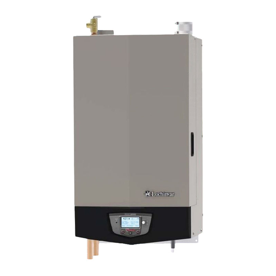
Lochinvar Knight WHN055 Installation & Operation Manual
Wall mount boiler
Hide thumbs
Also See for Knight WHN055:
- Installation & operation manual (80 pages) ,
- Installation & operation manual (80 pages) ,
- Installation & operation manual (80 pages)
Table of Contents
Advertisement
WH-I-O Rev K
Installation & Operation Manual
Models: WH 55 - 399
This manual must only be used by
WARNING
a qualified heating installer / service
technician. Read all instructions,
including this manual and the Knight
Wall Mount Service Manual, before
installing. Perform steps in the order
given. Failure to comply could result
in severe personal injury, death, or
substantial property damage.
Save this manual for future reference.
Advertisement
Table of Contents

Related Manuals for Lochinvar Knight WHN055


Summary of Contents for Lochinvar Knight WHN055
- Page 1 This manual must only be used by WARNING a qualified heating installer / service technician. Read all instructions, including this manual and the Knight Wall Mount Service Manual, before installing. Perform steps in the order given. Failure to comply could result in severe personal injury, death, or substantial property damage.
-
Page 2: Table Of Contents
Sequence of Operation ..... . . 68-69 Multiple Vent/Air Terminations ......... 25 Knight Wall Mount Boiler Control Module ... . 70 Sidewall Termination - Optional Concentric Vent ..26-28 Status Display Screens . -
Page 3: Please Read Before Proceeding
Please read before proceeding When servicing boiler – Installer – Read all instructions, WARNING including this manual and the Knight • To avoid electric shock, disconnect electrical supply Wall Mount Service Manual, before before performing maintenance. installing. Perform steps in the order given. -
Page 4: The Knight Wall Mount Boiler - How It Works
Installation & Operation Manual The Knight Wall Mount Boiler - How it works... Stainless steel heat exchanger 15. Gas connection pipe Allows system water to flow around specially designed Threaded pipe connection. This pipe should be tubes for maximum heat transfer, while providing connected to the incoming gas supply for the purpose of protection against flue gas corrosion. - Page 5 Installation & Operation Manual The Knight Wall Mount Boiler - How it works... (continued) Models 55 - 399 FRONT OF UNIT IMG00117 Front View Bottom View IMG00162 IMG00161 Left Side (inside unit) Right Side (inside unit)
-
Page 6: Ratings
*Note: WHN399 value is thermal efficiency. Maximum allowed working pressure is located on the rating plate. NOTICE 7. The Knight Wall Mount boiler input rate, on some models, Notes: is reduced for vent lengths beyond the minimum. Two inch 1. As an Energy Star Partner, Lochinvar has determined that... -
Page 7: Determine Boiler Location
The two ventilating air 4. The Knight wall mount boiler must be installed so openings shown in FIG. 1-1 are required that gas control system components are protected from for this arrangement. Failure to follow... - Page 8 Installation & Operation Manual Determine boiler location Figure 1-1 Closet Installation - Minimum Required Clearances For closet installations, CPVC, WARNING LEFT polypropylene or stainless steel 6" MINIMUM 0" MINIMUM vent material MUST BE used in VENTILATING a closet structure due to elevated AIR OPENING temperatures.
-
Page 9: Provide Air Openings To Room
Ensure the wall for which the boiler is intended to be mounted is comprised of either, cement, brick, block, or Install air inlet piping for the Knight wall mount boiler as wooden studs spaced 16" apart from center. Ensure the described in this manual. -
Page 10: Corrosive Contaminants And Sources
Installation & Operation Manual Determine boiler location When using an existing vent system to Table 1A Corrosive Contaminants and Sources install a new boiler: Products to avoid: Failure to follow all instructions can result WARNING Spray cans containing chloro/fluorocarbons in flue gas spillage and carbon monoxide emissions, causing severe personal injury Permanent wave solutions or death. -
Page 11: Removing A Boiler From Existing Common Vent
Determine boiler location (continued) When removing a boiler from existing common vent system: Do not install the Knight wall mount g. Any improper operation of the common venting system DANGER should be corrected so the installation conforms with boiler into a common vent with any other the National Fuel Gas Code, ANSI Z223.1/NFPA 54... -
Page 12: Prepare Boiler
You must install the propane orifice to fire the gas valve and secure inside the gas valve (see FIG. 2-3). the Knight wall mount boiler on propane. Verify when installing that the orifice size 11. Reattach the venturi to the gas valve and reposition the gas marking matches boiler size (Table 2A). -
Page 13: Mounting The Boiler
(2) field supplied toggle bolts. instructions. WARNING The boiler is too heavy for a single person The Knight Wall Mount boiler is not NOTICE to lift. A minimum of two people is needed intended for floor installation. -
Page 14: General Venting
Installation & Operation Manual General venting Direct venting options - Sidewall Vent Figure 3-1 Two-Pipe Sidewall Termination - See page Figure PVC/CPVC Concentric Sidewall 22 for more details Termination - See page 26 for more details Figure 3-4 PVC/CPVC Concentric Figure 3-5 Vertical Vent, Sidewall Air Figure 3-3 Two-Pipe Vertical Vertical Termination - See page 30... -
Page 15: Install Vent And Combustion Air Piping
General venting Install vent and combustion air piping The Knight wall mount boiler must be The Knight wall mount boiler vent and air piping can be DANGER vented and supplied with combustion and installed through the roof or through a sidewall. Follow the ventilation air as described in this section. -
Page 16: Requirements For Installation In Canada
Lochinvar (see Section 4 – Sidewall Termination – Optional Concentric Vent) and the 2" and 3" Concentric Vent Kits Equivalent Vent available from IPEX are approved for use on the Knight Model Kit Number Length wall mount boiler. Both kits are listed to the ULC-S636 standard for use in Canada. -
Page 17: Materials
Installation & Operation Manual General venting (continued) Materials Air inlet pipe materials: The PVC, CPVC, or ABS air inlet pipe should be cleaned and The air inlet pipe(s) must be sealed. Choose acceptable combustion air inlet pipe materials from the following list: sealed with the pipe manufacturer’s recommended solvents and standard commercial pipe cement for the material used. -
Page 18: Optional Room Air
When these chemicals pass through the boiler, they can form Commercial applications utilizing the Knight wall mount strong acids. The acid can eat through the boiler wall, causing boiler may be installed with a single pipe carrying the flue... -
Page 19: Pvc/Cpvc
Installation & Operation Manual General venting (continued) PVC/CPVC Work from the boiler to vent or air termination. Do not exceed the lengths given in this manual for the air or vent This product has been approved for use with the PVC/CPVC piping. -
Page 20: Polypropylene
Installation & Operation Manual General venting Polypropylene Use only the adapters and vent system listed WARNING in Tables 3E and 3F. DO NOT mix vent This product has been approved for use with polypropylene systems of different types or manufacturers. vent with the manufacturers listed in Table 3E. -
Page 21: Stainless Steel Vent
Installation & Operation Manual General venting (continued) Stainless steel vent Installation of a stainless steel vent NOTICE system should adhere to the stainless This product has been approved for use with stainless steel steel vent manufacturer’s installation using the manufacturers listed in Table 3G. instructions supplied with the vent system. -
Page 22: Determine Location
Installation & Operation Manual Sidewall direct venting Vent/air termination – sidewall Figure 4-1A PVC/CPVC/ Polypropylene Sidewall Follow instructions below when Termination of Air and Vent w/Field Supplied Fittings WARNING determining vent location to avoid FACTORY PROVIDED possibility of severe personal injury, BIRD SCREEN death, or substantial property damage. -
Page 23: Sidewall Direct Venting Vent/Air Termination - Sidewall
Installation & Operation Manual Sidewall direct venting (continued) Vent/air termination – sidewall 6. Locate terminations so they are not likely to be damaged Figure 4-1C Alternate PVC/CPVC/SS/ Polypropylene Venting by foreign objects, such as stones or balls, or subject to Arrangement (if Space Allows) w/Field Supplied Fittings buildup of leaves or sediment. -
Page 24: Prepare Wall Penetrations
Installation & Operation Manual Sidewall direct venting Figure 4-3B Alternate Clearance to Forced Air Inlets w/ Figure 4-4A PVC/CPVC Sidewall Termination Assembly Field Supplied Fittings IF LESS THAN 10’ 36” VENT MIN. FORCED AIR AIR PIPING CENTERLINE WIDTH INLET BIRD VENT PIPING SCREEN VENT PLATE... -
Page 25: Multiple Vent/Air Terminations
Canadian installations, provide clearances required by CSA B149.1 Installation Code. 3. The air inlet of a Knight wall mount boiler is part of a direct vent connection. It is not classified as a forced air intake with regard to spacing from adjacent boiler vents. -
Page 26: Sidewall Termination - Optional Concentric Vent
Installation & Operation Manual Sidewall direct venting Sidewall termination – optional concentric vent Description and usage Lochinvar offers optional concentric combustion air and vent 3. Cut one (1) hole (5 inch diameter for #CVK3003 pipe termination kits (Factory Kit #CVK3003 for 3" diameter installations, 4 inch diameter for #CVK3008, or 7 inch - models 155 - 199, #CVK3008 for 2"... - Page 27 Installation & Operation Manual Sidewall direct venting (continued) Sidewall termination – optional concentric vent models Figure 4-9 2" and 3" Concentric Vent Dimensional Figure 4-10 4" Concentric Vent Dimensional Drawing Drawing (reference Table 3D on page 19) (reference Table 3D on page 19) "B"...
- Page 28 Installation & Operation Manual Sidewall direct venting Sidewall termination – optional concentric vent Figure 4-12 Concentric Vent Sidewall Attachment Multiventing sidewall terminations DO NOT use field-supplied couplings to CAUTION extend pipes. Airflow restriction will occur When two (2) or more direct vent appliances are vented near and may cause intermittent operation.
-
Page 29: Vertical Direct Venting
Installation & Operation Manual Vertical direct venting Vent/air termination – vertical Figure 5-1A PVC/CPVC/Polypropylene Vertical Termination of Air and Vent Follow instructions below when WARNING ALTERNATE INTAKE LOCATIONS: determining vent location to avoid INTAKE PIPES MAY BE LOCATED possibility of severe personal injury, death ANYWHERE WITHIN 24”... -
Page 30: Multiple Vent/Air Terminations
FIG. 5-2). For Canadian installations, provide clearances required by CSA B149.1 Installation Code. 3. The air inlet of a Knight wall mount boiler is part of a direct vent connection. It is not classified as a forced air intake with regard to spacing from adjacent boiler vents. - Page 31 Installation & Operation Manual Vertical direct venting (continued) Ensure termination height is above the Instead of cementing the smaller pipe to NOTICE NOTICE roof surface or anticipated snow level (12 the rain cap, a field supplied stainless steel inches in U.S.A. or 18 inches in Canada) as screw may be used to secure the two (2) shown in FIG.
-
Page 32: Alternate Vertical Concentric Venting
Installation & Operation Manual Vertical direct venting Alternate vertical concentric Figure 5-8 Concentric Vent Example 1 venting FLUE EXHAUST This appliance may be installed with a concentric vent arrangement where the vent pipe is routed through an SEAL existing unused venting system; or by using the existing COMBUSTION AIR unused venting system as a chase for vent and combustion AIR INLET... -
Page 33: Hydronic Piping
Hydronic piping System water piping methods General piping information The Knight wall mount is designed to function in a closed Basic steps are listed below along with illustrations on the loop pressurized system not less than 12 psi. A temperature following pages (FIG.’s 6-3 through 6-12), which will guide... -
Page 34: Near Boiler Piping Components
20 feet of piping, 4 - 90° elbows, and 2 - fully 13. Indirect water heaters: ported ball valves. The Knight wall mount boiler may be piped to an indirect water heater to heat domestic hot water with the space heat Knight wall mount boilers are capable of controlling a transfer medium. -
Page 35: Near Boiler Piping Connections
Circulator sizing The Knight wall mount boiler heat exchanger does have a pressure drop, which must be considered in your system design. Refer to the graph in FIG. 6-2 for pressure drop through the Knight wall mount boiler heat exchanger. - Page 36 Installation & Operation Manual Hydronic piping Figure 6-2 Pressure Drop vs. Flow 3.00 9.00 8.00 2.50 7.00 MODEL MODEL 2.00 6.00 5.00 1.50 4.00 1.00 3.00 2.00 0.50 1.00 0.00 0.00 -0.50 FLOW FLOW 3.50 3.00 2.00 1.80 2.50 1.60 MODEL MODEL 1.40...
-
Page 37: Variable Speed Pump Option
20 feet of piping, 4 - 90° elbows, and 2 - fully ported ball valves. The Knight wall mount boiler is capable of producing up It is recommended that near boiler to three (3) set point temperatures to meet different space... - Page 38 Installation & Operation Manual Hydronic piping Figure 6-3 Single Boiler - Primary / Secondary Piping PRESSURE REDUCING VALVE PRESSURE BACKFLOW GAUGE PREVENTER MAKE UP WATER SEPARATOR SYSTEM SUPPLY SENSOR MAY SUBSTITUTE LOW LOSS HEADER FROM SYSTEM SYSTEM NOT TO EXCEED 4 PIPE DIA OR MAX. OF 12" APART SYSTEM BALL VALVE CIRCULATOR...
- Page 39 Installation & Operation Manual Hydronic piping (continued) Figure 6-4 Single Boiler - Single Temperature with Zone Valves - DHW Priority ZONE #1 PRESSURE PRESSURE REDUCING VALVE GAUGE ZONE #2 ZONE #3 ZONE #4 BACKFLOW PREVENTER ZONE VALVES (TYPICAL) MAKE UP WATER DIFFERENTIAL PRESSURE...
- Page 40 Installation & Operation Manual Hydronic piping Figure 6-5 Single Boiler - Single Temperature Zoned with Circulators - DHW Priority ZONE #1 PRESSURE PRESSURE GAUGE REDUCING VALVE ZONE #2 ZONE #3 ZONE #4 BACKFLOW FLOW CHECK PREVENTER VALVE (TYPICAL) MAKE UP WATER SYSTEM SUPPLY SENSOR ZONE CIRCULATORS...
- Page 41 Installation & Operation Manual Hydronic piping (continued) Figure 6-6 Multiple Boilers - Single Temperature Zoned with Zone Valves - DHW Priority Number of Units Model Required Pipe Sizes 1-1/4" 1-1/2" 1-1/2" 2" 2" 2" 2" 1-1/4" 1-1/2" 2" 2" 2" 2-1/2"...
- Page 42 Installation & Operation Manual Hydronic piping Figure 6-7 Multiple Boilers - Single Temperature Zoned with Circulators - DHW Priority Number of Units Model Required Pipe Sizes 1-1/4" 1-1/2" 1-1/2" 2" 2" 2" 2" 1-1/4" 1-1/2" 2" 2" 2" 2-1/2" 2-1/2" 1-1/2"...
- Page 43 Installation & Operation Manual Hydronic piping (continued) Figure 6-8 Single Boiler - Multiple Temperature - DHW Priority PRESSURE TEMPERATURE TEMPERATURE TEMPERATURE REDUCING VALVE LOOP #1 LOOP #2 LOOP #3 BACKFLOW PREVENTER PRESSURE GAUGE MAKE MIXING VALVES SYSTEM WATER (TYPICAL) SUPPLY SENSOR AIR SEPARATOR EXPANSION...
- Page 44 Installation & Operation Manual Hydronic piping Figure 6-9 Multiple Boilers - Multiple Temperature - DHW Piped as a Zone Number of Units Model Required Pipe Sizes 1-1/4" 1-1/2" 1-1/2" 2" 2" 2" 2" 1-1/4" 1-1/2" 2" 2" 2" 2-1/2" 2-1/2" 1-1/2"...
- Page 45 Installation & Operation Manual Hydronic piping (continued) Figure 6-10 Single Boiler - Full Flow - Single Temperature - Zoned with Zone Valves - DHW Priority ZONE #1 PRESSURE PRESSURE REDUCING VALVE GAUGE ZONE #2 ZONE #3 ZONE #4 BACKFLOW PREVENTER ZONE VALVES (TYPICAL) MAKE UP...
- Page 46 Installation & Operation Manual Hydronic piping Figure 6-11 Single Boiler - Full Flow - Single Temperature Zoned with Valves - DHW Piped as a Zone ZONE #1 PRESSURE REDUCING VALVE PRESSURE ZONE #2 ZONE #3 ZONE #4 GAUGE BACKFLOW PREVENTER ZONE VALVES (TYPICAL) MAKE UP...
- Page 47 Installation & Operation Manual Hydronic piping (continued) Figure 6-12 Single Boiler - Full Flow - Single Temperature Zoned with Circulators - DHW Piped as a Zone ZONE #1 PRESSURE PRESSURE GAUGE REDUCING VALVE ZONE #2 ZONE #4 ZONE #3 BACKFLOW FLOW CHECK PREVENTER VALVE...
-
Page 48: Gas Connections
Installation & Operation Manual Gas connections Connecting gas supply piping 1. Remove the front access panel and refer to FIG. 7-1 2. Support piping with hangers, not by the boiler or its to pipe gas to the boiler. accessories. Install a field supplied sediment trap / drip leg The gas valve and blower will not support upstream of the boiler gas controls. -
Page 49: Natural Gas
14 inches w.c. maximum. Figure 7-2 Inlet Pipe with Backup Wrench Propane Gas: WARNING Knight wall mount boilers are typically shipped ready to fire on natural gas. Check boiler rating plate to determine which fuel the boiler is set for. If set to natural gas, it may be converted to LP by installing an orifice (see page 13). -
Page 50: Check Inlet Gas Supply
5640 5130 4720 Knight wall mount boilers are typically shipped ready to fire on natural gas. Check boiler rating plate to WARNING determine which fuel the boiler is set for. If set to natural gas, it may be converted to LP by installing an orifice (see page 13). -
Page 51: Gas Pressure
(dynamic) mode. If an in-line regulator is used, it must be a use the bubble test or check for gas leaks minimum of 10 feet from the Knight wall mount boiler. It is can cause severe personal injury, death, very important that the gas line is properly purged by the gas or substantial property damage. -
Page 52: Field Wiring
Installation & Operation Manual Field wiring Line voltage connections ELECTRICAL SHOCK HAZARD – For your 1. Remove bezel as shown in FIG. 8-1. WARNING safety, turn off electrical power supply before 2. Connect 120 vac power wiring to the line voltage terminal making any electrical connections to avoid strip in the junction box, as shown in FIG. -
Page 53: Outdoor Temperature Sensor
2. Remove the jumper wire from these terminals and connect outdoor sensor terminals on the connection board to these terminals to the normally open contacts on the flow enable outdoor reset operation of the Knight wall mount switch (FIG. 8-4). boiler. Residential boilers with inputs less than 300,000... -
Page 54: Wiring Of The Cascade
SYSTEM control to use the inlet sensor as the controlling as the Leader boiler. The remaining boilers will be designated sensor. See the Knight Wall Mount Service Manual for as Members. See page 63 “Configuration of the Cascade” for a instructions on how to do this. - Page 55 Installation & Operation Manual Field wiring (continued) Figure 8-4 Low Voltage Field Wiring Connections...
-
Page 56: Condensate Disposal
Condensate horizontal runs, a second line vent may be from the Knight wall mount boiler will be slightly acidic required and tubing size may need to increase (typically with a pH from 3 to 5). Install a neutralizing to 1 inch. -
Page 57: Startup
Starting on the lowest floor, open air vents one at a 4. The freeze protection set points may be lowered when time until water squirts out. freeze protection fluid is used (see the Knight Wall Repeat with remaining vents. Mount Service Manual). -
Page 58: Check For Gas Leaks
Installation & Operation Manual Start-up Check for gas leaks Inspect/fill condensate system Before starting the boiler, and during Inspect/check condensate lines and fittings WARNING initial operation, smell near the floor and 1. Inspect the condensate drain line, condensate fittings and around the boiler for gas odorant or any condensate trap. -
Page 59: Start The Boiler
Final checks before starting the boiler Check vent piping and air piping 1. Check for gas tight seal at every connection, seam of air Read the Knight Wall Mount Service Manual to piping, and vent piping. familiarize yourself with SMART SYSTEM control module operation. - Page 60 Installation & Operation Manual Start-up Figure 10-2 Operating Instructions - Models 55 - 285...
- Page 61 Installation & Operation Manual Start-up (continued) Figure 10-3 Operating Instructions - Model 399...
-
Page 62: Set Space Heating Operation
5 seconds to place the boiler into Service Mode. be changed in the control. See the Knight Wall Mount Service In Service Mode the boiler will fire at ignition speed and Manual for a detailed explanation of this procedure. - Page 63 NOTICE depending on the System Pump Mode selected (reference Daylight Savings Time and therefore, will the Knight Wall Mount Service Manual for details). In this require a manual adjustment. mode, any low temperature zones (such as radiant heating) may need additional controls to limit the water temperature The clock is automatically updated whenever a PC is connected sent to those zones.
-
Page 64: Operating Information
The Knight wall mount boiler can also be programmed to exchanger and flue piping. The control module regulates accept a call for heat from a 0 - 10V signal, reference the Knight blower speed to control the boiler firing rate. The gas valve... -
Page 65: Temperature Control
Protection features Modulation Outlet temperature, flue temperature, and temperature The Knight wall mount boiler is capable of modulating its rise limiting firing rate from a minimum of 20% to a maximum of 100%. The firing rate is dictated by the call for heat (i.e., space... - Page 66 Operating information Monitor external limits High limit operations The Knight wall mount is equipped with adjustable automatic Connections are provided on the connection board for reset and manual reset high limits. The automatic reset high external limits such as flow switch, low water cutoff, gas limit has a maximum set point of 200°F and the manual reset...
-
Page 67: Cascade
+ the turn-off offset - the off-on differential, then the control will initiate a call for heat on Ramp Delay operation of the boilers as described in the Knight the Cascade (see the Knight Wall Mount Service Manual for Wall Mount Service Manual is not active when the boilers are an explanation of the offset and differential). -
Page 68: Sequence Of Operation
Installation & Operation Manual Operating information Sequence of operation OPERATION DISPLAY 1. Upon a call for heat, the gas pressure switch(es) must be closed. 2. Once the gas pressure switch(es) are closed, the control turns on the appropriate pumps (system and boiler pumps for space heating, DHW pump for DHW). -
Page 69: Access Modes
Most parameters are available only to the installer, accessible To enter a parameter and continue programming: by entering the installer password, see the Knight Wall Mount Press the RIGHT SELECT [SAVE] key 1 time to return to the Service Manual. -
Page 70: Knight Wall Mount Boiler Control Module
Installation & Operation Manual Operating information Knight wall mount boiler control module Use the control panel (FIG. 11-1) to set temperatures, operating conditions, and monitor boiler operation. Figure 11-1 Control Panel NAVIGATION DIAL The information on the bottom of the display shows the functions of the two SELECT keys (on either corner), and the... -
Page 71: Status Display Screens
Installation & Operation Manual Operating information (continued) Figure 11-2 Status Display Screen (CALL FOR (BOILER HEAT) STATUS) (OPERATIONAL INFORMATION) (RIGHT SELECT KEY) (LEFT SELECT KEY) (NAVIGATION DIAL) Status Display Screens Section Display Description The unit has not received a call for heat from a remote thermostat nor STANDBY has it received a call for heat from a DHW thermostat. - Page 72 Installation & Operation Manual Operating information Status Display Screens (cont’d) Section Display Description SYSTEM: The temperature read by the system supply sensor (if connected). TANK: The temperature read by the tank sensor (if connected). OUTDOOR: The temperature read by the outdoor sensor (if connected). INLET TEMP: The temperature read at the inlet to the heat exchanger.
- Page 73 Installation & Operation Manual Operating information (continued) Status Display Screens (cont’d) Section Display Description Press and hold the LEFT SELECT key for 5 seconds to enter the Menu MENU Screen. EXIT Press the LEFT SELECT key to exit the current screen or setting. Press the LEFT SELECT key to confirm that the boiler needs to shutdown.
-
Page 74: Maintenance Maintenance And Annual Startup
Maintenance Maintenance and annual startup Table 12A Service and Maintenance Schedules Owner maintenance Service technician (see the Knight Wall Mount User’s Information (see the following pages for instructions) Manual for instructions) General: • Address reported problems • Check boiler area •... -
Page 75: Address Reported Problems
Section 1 of this manual. If any of these are present in the boiler intake air vicinity, they must be removed. If they cannot be removed, reinstall the air and vent lines per this manual and the Knight Wall Mount Service Manual. Inspect boiler interior 1. -
Page 76: Check Expansion Tank
Knight Wall Mount Service Manual. Adjust settings if water from the valve to a proper place of necessary. See Section 1 of the Knight Wall Mount Service disposal. Otherwise severe personal injury Manual for adjustment procedures. -
Page 77: Review With Owner
If cleaning the flame sense electrode does not improve, ground wiring is in good condition, 1. The circulator shipped with the Knight wall mount boiler is and ground continuity is satisfactory, replace the flame water-lubricated. No oiling is required. -
Page 78: Diagrams
Installation & Operation Manual Diagrams Figure 13-1 Ladder Diagram 120VAC JUNCTION BOX NEUTRAL GROUND TERMINAL STRIP TERMINAL STRIP 120V SUPPLY "L" 120V SUPPLY "N" INTEGRATED CONTROL BLOWER ON / OFF SWITCH SYSTEM X1-1 SYSTEM X1-6 PUMP "L" PUMP "N" X1-2 3.15A SYSTEM PUMP... -
Page 79: Wiring Diagram
Installation & Operation Manual Diagrams (continued) Figure 13-2 Wiring Diagram LOW VOLTAGE BOX DEPICTS 120 VAC OPTIONAL ITEMS HIGH VOLTAGE BOX DEPICTS DUAL SENSOR SINGLE HOUSING INTEGRATED BOX DEPICTS CONNECTION BOARD CONTROL JUNCTION OPTIONAL ITEMS ALARM X1-3 CONTACTS PUMP RUN-TIME CONTACTS X1-4 24 VAC LOUVER... - Page 80 Revision A (ECO #C06854) initial release. Revision B (ECO #C08222) reflects the changes to the water pipe clearances from 1" to a 1/4" (ECR #R04077), pages 7, 8, and 33 and changes made to the service clearances (left side) from 24" to 12" (ECR R04002).
Need help?
Do you have a question about the Knight WHN055 and is the answer not in the manual?
Questions and answers