3M Aqua-Pure AWS100M Installation And Operating Instructions Manual
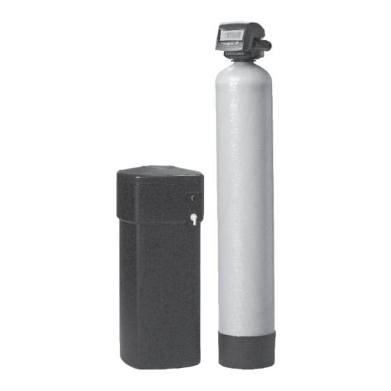
Aws series residential water softeners
Hide thumbs
Also See for Aqua-Pure AWS100M:

Related Manuals for 3M Aqua-Pure AWS100M


Summary of Contents for 3M Aqua-Pure AWS100M
- Page 1 INSTALLATION AND OPERATING INSTRUCTIONS AWS SERIES RESIDENTIAL WATER SOFTENERS MODELS: AWS100M AWS150M AWS200M AWS300M Installer, please leave with homeowner. Homeowner, retain for future reference. INSTR2198 0911...
-
Page 3: Safety Information
• Utilize a NIOSH-approved dust fi lter mask, protective gloves, and appropriate eye protection when handling and pouring gravel and fi lter media. • To request an MSDS relating to this product, call 203-238-8965 or go to www.3M.com , select country, and use the search engine to search MSDS. For emergen- cies, call 800-364-3577 or 651-737-6501 (24 hours). - Page 5 TABLE OF CONTENTS SECTION DESCRIPTION BEFORE INSTALLATION INSTALLATION PROGRAMMING SERVICE INSTRUCTIONS & MAINTENANCE PERFORMANCE DATA SHEET TROUBLESHOOTING PARTS LIMITED WARRANTY SECTION 1: BEFORE INSTALLATION CAUTION To reduce the risk associated with property damage due to water leakage: • Read and follow Use instructions before installation and use of this water treatment system. •...
- Page 6 GENERAL Observe all warning and caution statements that appear in this manual. Keep the media tank in the upright position. Do not turn upside down or drop. Turning the tank upside down will cause media to enter the valve. Operating temperature is between 40°F (4.4°C) and 110°F (43.3°C). Rated water pressure range is 20 - 125 psi.
- Page 7 SECTION 2: INSTALLATION Proper installation sequence of water conditioning equipment is very important. Refer to the following diagram for your particular water supply. Failure to follow installation, operation, and maintenance instructions may result in property damage due to leakage and will void warranty. TYPICAL WELL INSTALLATION FILTERED WATER FILTERED...
- Page 8 Step 1) Remove the unit from the shipping box and remove all packaging. Ensure no freight damage has occurred since shipment from our manufacturing facility. Locate the parts package and install the bypass and adapter fi ttings on the control valve to facilitate the connection to the customer’s water supply.
- Page 9 Step 10) Make certain BYPASS VALVE INLET and OUTLET KNOBS ARE IN “BYPASS” position. After all plumbing connections have been completed, open main water shut-off valve and restore power to well pump. Check for leaks and correct as necessary. Figure 3 Step 11) Plug CONTROL VALVE POWER CORD into 110v/60Hz, non-switched power source.
-
Page 10: Electrical Connection
BRINE LINE CONNECTION The brine line to the brine tank connects to the valve. Make the connections and tighten (See Figure 4). Be sure that the brine line is secure and free from air leak. Even a small leak may cause the brine line to drain out, and the conditioner will not draw brine from the tank. -
Page 11: Display Icons
MOTOR The controller uses a standard 12-volt AC motor that works with either 50 Hz or 60 Hz. IMPORTANT NOTE Water fl ow to the valve can be turned on or bypassed when the controller is powered up for the fi rst time. VARIABLE RESERVE FUNCTION The AWS metered-demand volumetric controllers are designed to have a variable reserve feature. - Page 12 21) Shows when water is fl owing through the valve. 22) Used with #23, #24, #25. Displays a sequence number or a value. 23) History Values. The number displayed by #22 identifi es which history value is currently displayed. 24) Parameter. Displayed only in Professional Programming. The number displayed by #22 identifi es which parameter is currently displayed. 25) Cycle.
- Page 13 REGENERATION MODES The AWS series controllers can be regenerated either automatically or manually. During a regeneration, the total time remaining of the regeneration, the total time remaining of the regeneration will be displayed on the controller. The current cycle is shown in the lower left of the display. Regeneration Cycle Indicators C0 = Treated Water - normal operation mode (not displayed) C1 = Backwash Cycle...
-
Page 14: Manual Regeneration
MANUAL REGENERATION Action Duration Display Regen at next time of regen REGEN Recycle icon fl ashes Cancel regen REGEN P/R when recycle icon is fl ashing Recycle icon disappears Immediate regen REGEN 5 sec. Recycle icon appears Immediate double regen REGEN 5 sec. - Page 15 START-UP IMPORTANT NOTE The control valve can be started-up even if power is not yet available to the controller. The valve must be connected to water supply. The motor can be unmounted from the valve, and the camshaft can be indexed manually counterclockwise by hand. This will allow the tank to be fi lled and allows regenerant draw to be tested. See Drive Motor of this manual for further instructions.
- Page 16 IMPORTANT NOTE As you advance through each cycle there will be a slight delay before you can advance to the next cycle. The hourglass icon will light while the camshaft is index- ing. There may be a pause at cycle C4 (System Pause). This cycle allows the water/air pressure to equalize on each side of the valve discs before moving on. The hourglass will not be visible indicating that the system is paused.
- Page 17 SECTION 3: PROGRAMMING • When the controller is fi rst plugged in, it may display a fl ashing hourglass and the message Err 3, this means that the controller is rotating to the home position (FIgure 14). If the Err 2 is displayed, check that the incoming power frequency matches the controller. See the Troubleshooting section of this manual. •...
- Page 18 This level of programming is accessible by pressing the SET button. The UP and DOWN arrows will step through the settings. Time of day Day of week Time of regeneration Number of days between regeneration (99 day calendar override timer) Amount of salt used per regeneration System capacity Hardness...
- Page 19 • Calendar override The controller can be programmed to regenerate automatically from a 1/2 day to a 99 day frequency. The 1/2 day regeneration mode will regenerate at the “time of regeneration,” as well as 12 hours opposite from that time. For example, the controller will regenerate at 2:00 AM and at 2:00 PM on the same day.
- Page 20 The following tables show the estimated salt amount for each setting, as well as the estimated capacity of that salt setting for each resin amount. Media Volume Salt Setting Total Salt Amount per Regeneration (lbs) L (Low) S (Standard) H (High) L (Low) 5.25 S (Standard)
- Page 21 History Data Description Range Resin volume initial setting value cubic feet Days since last regeneration 0-255 Current fl ow rate 0-47 gpm Water used today in gallons since Time of Regeneration 0-65536 gallons Water used since last regeneration in gallons 0-65536 gallons Total water used since reset in 100s 0-65536 gallons...
- Page 22 SECTION 4: SERVICE INSTRUCTIONS & MAINTENANCE VALVE SERVICE COVER The cover provides protection for the controller, wiring, and other components. This cover will be removed for most service and maintenance. To remove cover: 1) Grasp side edges toward rear of the valve. 2) Pull outwards until the slots in the cover clears the projections on the top plate.
- Page 23 DRIVE MOTOR The drive motor is open loop and receives commands from the control module. The motor has a pinion gear that meshes with the camshaft gear to drive (rotate) the camshaft. During operation, rotation forces the motor into its mounting position and screws or bolts are not needed. NOTE: Some units will have a shipping peg in the top motor mount.
- Page 24 CAMSHAFT The camshaft has several lobes that push open the valve discs as the camshaft rotates. Rotation is controlled by a drive motor that drives a gear at the rear of the camshaft. The front end has a cup with markings and slots. IMPORTANT NOTE The camshaft slots are molded to exact dimensions.
- Page 25 WIRING HARNESSES The wiring harnesses are designed to fi t one way. The connectors are unique to the port they plug into. The wires are held in place by clips and the connectors latch in place. Figure 31 To remove a wiring harnesses: 1) Disconnect power to the unit.
- Page 26 SPRING (VALVE DISCS) This spring is a one-piece metal spring that applies pressure to the valve discs holding them closed. The rotating camshaft overcomes this pressure to open the valve discs as needed. The shape of the spring is critical for proper operation. IMPORTANT NOTE Do not attempt to straighten or repair this spring.
- Page 27 TOP PLATE The top plate holds the valve discs in place during operation. This plate is removed to allow cleaning and replacing the valve discs. IMPORTANT NOTE The valve discs are made from a chloramine resistant severe service rubber. The valve discs will usually not need to be changed. Before removing the top plate for valve disc service be certain that one of the discs is not operating correctly.
- Page 28 10) Replace camshaft and motor. 11) Replace controller and wiring harnesses. Figure 37 MAINTENANCE IMPORTANT NOTE: Many of the maintenance procedures involve o-rings. When reassembling two parts with an o-ring seal, care must be taken with the placement of the o-ring. To properly install o-rings, they should be lightly lubricated with silicone.
- Page 29 WATER METER MAINTENANCE Demand Systems The valve metering devices are used with the demand controls, and may require simple maintenance. In rare instances, the turbine wheel of the water meter can collect small particles of oxidized iron, eventually preventing the wheel from turning. 1) Shut off the water supply or put the bypass valve(s) into the bypass position.
- Page 30 AFTER SERVICE START-UP Whenever the controller is unplugged or the system is put in bypass for maintenance, a start-up is required. This start-up is not normally as extensive as the new system start-up procedure needs to be followed. The initial power-up procedure should be used if a new controller or a new valve has been installed. This procedure is explained in the users manual. The following service start-up procedure can be used when the controller was programmed prior to servicing the unit and removing power.
- Page 31 SECTION 5: PERFORMANCE DATA SHEET Model Number AWS100M AWS150M AWS200M AWS300M Rated Service Flow (gpm) 11.2 12.7 Pressure Drop at Rated Service Flow Rate (psi) Rated Softening Capacity (Grains) Low Salt Setting 15,115 @ 3.5 lbs salt 22,053 @ 5 lbs salt 28,864 @ 6.5 lbs salt 44,106 @ 10 lbs salt Standard Salt Setting...
- Page 32 SECTION 6: TROUBLESHOOTING PROBLEM CAUSE SOLUTION ERR 1 displayed A. Controller power has been connected and the A. Press the UP arrow and the control should reset. control is not sure of the state of operation. ERR 2 displayed A. Controller power does not match 50 or 60 Hz. A.
- Page 33 Clock does not display A. Electrical outlet operated by switch. A. Use electrical outlet not controlled by switch. correct time of day. B. Incorrect voltage or frequency (Hz). B. Replace timer with one of correct voltage and frequency (Hz) (Contact Dealer). C.
- Page 34 SECTION 7: PARTS COMPONENT PARTS LIST METERED SOFTENER MODELS (AWS SERIES) DESCRIPTION AWS100M AWS150M AWS200M AWS300M Control Valve, Timer & Cover (AWS-M) VAM-X-7SB-C VAM-X-5SB-C VAM-X-5SB-C VAM-X-8SB-C O-ring Media Tank w/Base 6236001-0844 6236001-1044 6236001-1054 MTP1465B Media H-10P H-010P & H-050P H-10P (x2) H-10P (x3) Turbulator 6236232...
- Page 35 VALVE EXPLODED VIEW VALVE PARTS LIST ONLY THOSE PARTS REFERENCED IN DRAWING ARE STOCK ITEMS ALL OTHERS ARE SPECIAL ORDER, NON-RETURNABLE PART NO. DESCRIPTION PART NO. DESCRIPTION 1035807 Valve Assembly w/o Flow Controls 1243510 Regenerant Refi ll Controller 1235338 Top Plate (Not Shown) 1030502 Ball, Refi...
- Page 36 OR USAGE OF TRADE. If the Product is found defective within the warranty period, your exclusive remedy and 3M Purifi cation Inc.’s sole obligation shall be, at 3M Purifi cation Inc.’s option, to replace or repair the Product or refund the purchase price of the Product. This warranty does not cover labor. The remedy stated in this paragraph is Customer’s sole remedy and 3M Purifi cation Inc.’s exclusive obligation.
Need help?
Do you have a question about the Aqua-Pure AWS100M and is the answer not in the manual?
Questions and answers