Table of Contents
Advertisement
Our Focus - Your Peace of Mind
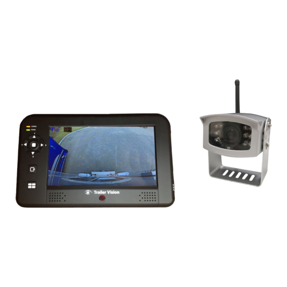
Digi-Max2
Digital Wireless Camera System
Installation and User Manual
PLEASE READ CAREFULLY AND SAVE
This manual contains important information about this
product's operation. If you are installing this product for others,
you must leave this manual, or a copy, with the end user.
Version 1.0
Advertisement
Table of Contents

Related Manuals for Trailer Vision Digi-Max2


Summary of Contents for Trailer Vision Digi-Max2
- Page 1 Our Focus - Your Peace of Mind Digi-Max2 Digital Wireless Camera System Installation and User Manual PLEASE READ CAREFULLY AND SAVE This manual contains important information about this product’s operation. If you are installing this product for others, you must leave this manual, or a copy, with the end user.
-
Page 2: Table Of Contents
CONTENTS INTRODUCTION ................2 KEY FEATURES ............... 2 IMPORTANT SAFETY PRECAUTIONS ........2 INSTALLING THE CAMERA ............5 With fixed power source ............5 Using the trigger cable............... 5 With battery pack (not included in the package) ......5 INSTALLING THE MONITOR ............6 GETTING TO KNOW THE CAMERA .......... -
Page 3: Introduction
INTRODUCTION KEY FEATURES: Digital Wireless Camera System, enabling up to 200m of secure video transmission Wireless Monitor with 7” LCD screen, video display from reversing etc. camera up to VGA@25FPS (single camera); or QVGA@20fps (multiple cameras) Supports up to 4 cameras, with revesing-camera set to CH1 (triggered) Wireless monitor support CH auto-switch functions, with a trigger cable connected between the monitor and the reversing light circuit;... - Page 4 FCC Compliance Statement: This Products with CE Marking comply with device complies with Part 15 of the EMC Directive (2004/108/EC); Low FCC rules. Operation is subjected to Voltage Directive (73/23/EEC); R&TTE(1999/5/EC); ROHS Directive the following two conditions: (1) this device may not cause harmful interference, (2011/65/EU) issued by the Commission of the and (2) this device must accept any interference European Community.
-
Page 5: Installing The Camera
INSTALLING THE CAMERA With a fixed power source: 1. For reversing, choose a location at the rear of the vehicle/trailer, ideally in the middle and as high up as possible (to give the best view). 2. Screw the camera mounting bracket to the desired location. Attach the camera to the bracket, making sure the camera &... -
Page 6: With Fixed Power Source
Using the trigger cable: Utilising the trigger cable enables the Channel 1 camera to be automatically displayed when reverse gear etc. is engaged. 1. Connect the trigger cable ring-shaped connectors to the fuse/ electrical circuit of the reversing lights. 2. Connect the other end of the trigger cable to the monitor. 3. -
Page 7: Installing The Monitor
INSTALLING THE MONITOR Screw the antenna to the cconnector at the top of the monitor. Secure the windscreen mount to the rear of the monitor (a dashboard mount is also available, not included). Secure the suction mount to the windscreen, ideally resting the base of the monitor on the vehicle dashboard. -
Page 8: Getting To Know The Camera
GETTING TO KNOW THE CAMERA 1. Camera Lens 2. Pairing Button 3. Mounting Bracket 4. IR LEDs 5. Light Sensor 6. Antenna 7. Power cord 8. Pairing LED Indicator 9. Power LED Indicator... -
Page 9: Getting To Know The Monitor
GETTING TO KN OW THE MONITOR Antenna Pairing Power Button Indicator Power Indicator Trigger Cable Power Adaptor Monitor Function Buttons Buttons Function Remote Controller (Menu Mode) [Cursor Up] / (QUAD View Mode) [Hot key CH1] (Menu Mode) [Cursor Right] / (QUAD View Mode) [Hot key CH2] (Menu Mode) [Cursor DOWN] / (QUAD View Mode) [Hot key CH3]... - Page 10 Monitor Display Icons Status Indicator Channel Indicator Signal Indicator Signal Indicator shows signal strength as below: Signal Level Indicator VGA Frame Rate QVGA Frame Rate Perfect 5~10 fps 15~30 fps Good 3~5 fps 12~20 fps Fair 2~4 fps 8~15 fps 0~1 fps 0~4 fps Zero...
-
Page 11: Configuring The Monitor
CONFIGURING THE MONITOR Press the Power button to switch the monitor ON. Press and hold to switch the monitor OFF . (MENU button) to enter/exit the Main menu. Press (Left / Right / Up / Down) buttons to navigate through menu items and change the settings. -
Page 12: Pairing Camera(S)
Pairing camera(s) Complete the Pairing process if an additional/new camera is utilised, or if the monitor doesn’t display a camera; use this process to pair the camera with the monitor. IMPORTANT: 1. To complete the Pairing process, ensure the camera is powered (reverse gear may need to be selected). -
Page 13: Brightness
4. Once pairing is completed, the monitor will display the camera image. Press the menu key again to save the pairing action and return to the main menu. Brightness Set up the brightness of the cameras for different environments (inside/ outside etc);... -
Page 14: Setting Scan Mode
2. Press (MENU button) to restore the default settings as below. Scan CAM1 CAM2 CAM3 CAM4 Pair CAM 1 2 3 4 Brightness Monitor CAM1 CAM2 CAM3 CAM4 Setting SCAN Mode Press the SCAN button to enter the SCAN mode and display camera channels automatically. - Page 15 IMPORTANT: 1. This function is for multi camera use/display. Before setting QUAD display, make sure that all cameras are paired to assigned channels. Please refer to the Pair CAM section for Pairing instructions. QUAD display will be restored to single camera display when a direction button (Left / Right / Up / Down) is pressed.
-
Page 16: Trouble Shooting
TROUBLE SHOOTING This section offers some helpful information to overcome most of the problems you may encounter. We hope this section can help you to enjoy a pleasant setup. Problem Possible Causes Solution System Message No power supply to Check lighting circuit & shows “NO Signal”... -
Page 17: About Digital Wireless Technology
ABOUT DIGITAL WIRELESS TECHNOLOGY This section offers some helpful information to solve most of the problems you may encounter. About 2.4GHz Digital Wireless Signal This innovative digital wireless solution integrates advance Frequency Hopping Spread spectrum (FHSS) technology. This technology greatly/completely reduces the interference from other devices using the same radio frequency (2.4GHz), e.g. -
Page 18: Product Specification
PRODUCT SPECIFICATION Camera Type: 1/4” CMOS Image Sensor Resolution: 640*480 Lens Type: Glass Lens Focal Length: 2.5MM Optical View Angle: Horizont al:87°±2°; Vertical:62°±2° Total IR LED: 10 PCS LED Angle: 120° Night Vision LED Wave Length: 850nm EDS Activate LUX: 1-8LUX Identified Range: 5-8m...
Need help?
Do you have a question about the Digi-Max2 and is the answer not in the manual?
Questions and answers