LG WM0742H*A Service Manual
Hide thumbs
Also See for WM0742H*A:
- User's manual & installation instructions (72 pages) ,
- User's manual & installation instructions (72 pages) ,
- Training manual (94 pages)
Table of Contents
Troubleshooting

Related Manuals for LG WM0742H*A


Summary of Contents for LG WM0742H*A
-
Page 1: Washing Machine
Website: http: //www.LGEservice.com E-mail: http: //www.LGEservice.com/techsup.html WASHING MACHINE SERVICE MANUAL CAUTION READ THIS MANUAL CAREFULLY TO DIAGNOSE TROUBLES CORRECTLY BEFORE OFFERING SERVICE. MODEL : WM0742H * A... - Page 2 SEP. 2007 PRINTED IN KOREA P/No.: MFL30599116...
-
Page 3: Table Of Contents
CONTENTS 1. SPECIFICATION ..........................3 2. FEATURES & TECHNICAL EXPLANATION ..................4 3. PARTS IDENTIFICATION ......................... 7 4. INSTALLATION & TEST ........................8 5. OPERATION ........................... 11 6. WIRING DIAGRAM/PROGRAM CHART ..................14 7. TROUBLE SHOOTING ........................15 7-1. BEFORE PERFORMING SERVICE ..................15 7-2. -
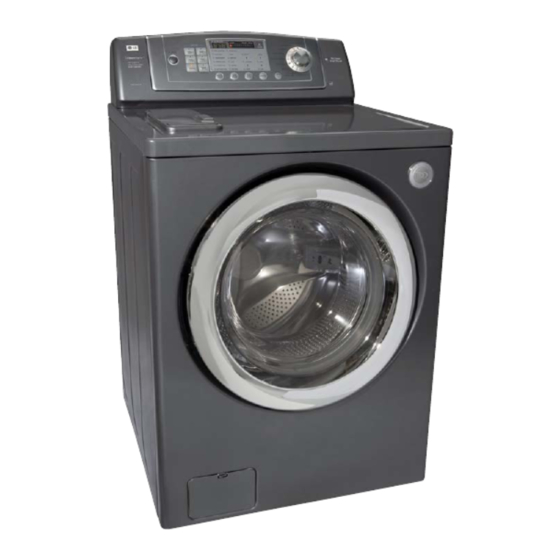
Page 4: Specification
1. SPECIFICATION ITEM WM0742H * A COLOR W:BLUE WHITE, G:PEARLY GRAY POWER SUPPLY AC 120 V, 60 Hz PRODUCT WEIGHT 192 lbs (87kg) WASHING 280 W ELECTRICITY 80 W DRAIN MOTOR CONSUMPTION 1000 W WASH HEATER WASH 46 rpm REVOLUTION SPIN 0-1200 rpm SPEED... -
Page 5: Features & Technical Explanation
2. FEATURES & TECHNICAL EXPLANATION 2-1. FEATURES Ultra Capacity The Larger drum enables not just higher head drop and stronger centrifugal force, but also less tangling and wrinkling of the laundry. Heavier loads, such as king size comforters, blankets, and curtains, can be washed. Direct Drive System The advanced Brushless DC motor directly drives the drum without belt and pulley. -
Page 6: Water Level Control
2-2. NEURO FUZZY WASHING TIME OPTIMIZATION To get the best washing performance, optimal time is determined by the water temperature, the selected washing temperature, and the size of the load. water temperature washing time the best selected NEURO- washing rinsing time washing FUZZY temperature... -
Page 7: Child Lock
2-5. THE DOOR CAN NOT BE OPENED While program is operating. When a power failed and power plug is taken out in operation. While Door Lock lights turn on. White the motor is in the process of intertial rotating, through the operation is paused. 2-6. -
Page 8: Parts Identification
3. PARTS IDENTIFICATION Control Panel Shipping Blots Power Plug Dispenser If the supply cord is damaged, it must be replaced by the manufacturer or its Drain Hose authorized service technician in order to avoid a hazard. Door Back of Washer Drum Air Vent for Safety Lower cover Cap... -
Page 9: Installation & Test
4. INSTALLATION & TEST Before servicing, ask the customer what the trouble is. Check the setup (power supply is 120 V AC, remove the transit bolts..). Check with the troubleshooting guide. Plan your service method by referring to the disassembly instructions. Service the unit. -
Page 10: How To Connect The Inlet Hose
HOW TO CONNECT THE INLET HOSE Verify that the rubber washer is inside of the valve connector. Tighten the inlet hose securely to prevent leaks. CONNECT DRAIN HOSE · Make sure that the hose is not twisted. · Avoid submerging the end of the hose. The end of the drain hose should be placed less than 96 from the floor. -
Page 11: Test Operation
7 TEST OPERATION Preparation for Press the POWER button. Press the Start/Pause button. washing. · Connect the power plug to the · Listen for a clicking sounds to outlet. determine if the door has locked. · Connect the inlet hose. Check the water heating Check the automatic Check the water supply. -
Page 12: Operation
5. OPERATION WM0742H * A STEAM... - Page 13 Power Button EST.TIME REMANING • Use this button to turn the • This display shows : power On/Off. a) the estimated time remaining in the cycle when operating. b) an error code when an error has been detected. START/PAUSE button •...
- Page 14 STATUS INDICATOR BEEPER button DOOR LOCKED lamp • These lights show elapsed time • Choose High/Low/Off. • Lights whenever the door is locked. of the selected cycle. • The door can be unlocked by pressing the Start/Pause button to stop the washer. CYCLE SELECTOR knob •...
-
Page 15: Wiring Diagram/Program Chart
6. WIRING DIAGRAM/PROGRAM CHART Base/Line MEZ31823211... -
Page 16: Troubleshooting
7. TROUBLESHOOTING 7-1. BEFORE PERFORMING SERVICE Be careful of electric shock when disconnecting parts while troubleshooting. The voltage of each terminal is 120 V AC and DC when the unit is plugged in. 7-2. QC TEST MODE The washer must be empty and the controls must be in the off state. 1. -
Page 17: Error Display
7-5. ERROR DISPLAY If you press the START/PAUSE button when an error is displayed, any error except will disappear and the machine will go into the pause status. In case of if the error is not resolved within 20 sec., or the in case of other errors, if the error is not resolved within 4 min., power will be turned off automatically and the error code will blink. - Page 18 ERROR SYMPTOM CAUSE • The connector (3-pin, male, white) in the MOTOR HARNESS is not connected to the connector (3-pin, female, white) of STATOR ASSEMBLY. • The electric contact between the connectors (3-pin, male, white) in the MOTOR HARNESS and LOCKED MOTOR 4-pin, female, white connector in the MAIN PWB ERROR...
-
Page 19: Error Diagnosis And Check List
8. ERROR DIAGNOSIS AND CHECK LIST 8-1. DIAGNOSIS AND SOLUTION FOR ABNORMAL OPERATION SYMPTOM GUIDE FOR SERVICE CALL No power Is the power plug connected firmly to 120 V AC outlet? Power failure? or Breaker opened? Is the outlet controlled by a switch? Visit to service Water inlet trouble displayed? - Page 20 SYMPTOM GUIDE FOR SERVICE CALL Door error Started with door opened? Close the door. Was the load too large? Avoid overloading. Clicking sound is heard once or twice, when the START/PAUSE button is pressed to start the cycle? Visit to service. Check if the door switch is OK.
- Page 21 SYMPTOM GUIDE FOR SERVICE CALL Suds overflow from the Is a HE(High Efficiency) detergent used? appliance. (In this condition, wash and spin do not operate normally) Is the proper amount of detergent used as recommended? Recommend to reduce the amount of detergent.
-
Page 22: Fault Diagnosis And Troubleshooting
8-2. FAULT DIAGNOSIS AND TROUBLESHOOTING CAUTION 1. Be careful of electric shock if disconnecting parts while troubleshooting. 2. First of all, check the connection of each electrical terminal with the wiring diagram. 3. If you replace the MAIN PWB ASSEMBLY, reinsert the connectors correctly. NO POWER Check the fuse or reset Is the supplied voltage 120V AC? - Page 23 VIBRATION & NOISE IN SPIN Have all the transit bolts and base Remove the transit bolts packing been removed? and Base packing. Is the washer installed on a solidly Move the washer or constructed floor? reinforce the floor. Check if the washer is perfectly level as follows: Check the leveling of the washer with a Level and check that the washer is stable.
-
Page 24: No Water Supply
NO WATER SUPPLY Is water supply shut-off? Is the tap opened? Open the tap. When you press both WASH/RINSE button and Check the AIR CHAMBER DELAY WASH button simultaneously, is the water and the tube (clogged). level frequency below 246? Is the inlet valve filter clogged? Clean the filter. -
Page 25: Abnormal Sound
LIQUID DETERGENT/SOFTENER/BLEACH DOES NOT FLOW IN Refer to Is water supplied? NO WATER SUPPLY Check the wiring on the Are the plugs correctly connected to the dispenser. terminals of the INLET VALVE ASSEMBLY? Put it in the correct Is liquid detergent/softenerbleach put in the compartment. -
Page 26: Heating Without Water
HEATING WITHOUT WATER When pressing SPIN SPEED and SOIL LEVEL at the same time after draining, is the water level frequency 255? Replace the SENSOR When pressing SPIN SPEED and SOIL LEVEL SWITCH ASSEMBLY. buttons at the same time while wash, is the water level frequency between 230 - 243? Check the voltage between two pins while Replace the MAIN PWB... - Page 27 WASH HEATER TROUBLE When checking the voltage between Replace the MAIN connector during whites washing. PWB ASSEMBLY. is the voltage 120V AC? After power off, is the resistance of wire (BN- BL) connectores between 10Ω ~ 30Ω? Normal After power off and the heater terminal Replace the is disconnected, is the resistance Heater Aseembly.
-
Page 28: Will Not Circulate Water
WILL NOT CIRCULATE WATER Is the impeller of the drain pump clogged? Remove foreign material Remove foreign material. Are the Hose Connector and/or Hose clogged? Reconnect or repair Is the connector disconnected, the connector. disassembled? Replace the PUMP Is the coil of the right side of drain pump open or short circited? (Coil R is 18~30Ω) MOTOR ASSEMBLY. -
Page 29: Spin Trouble
SPIN TROUBLE Check the SENSOR SWITCH ASSEMBLY or Check during spin if the frequency of the water HOSE (Pressure). level is 248 or more. If the problem is on the SENSOR SWITCH ASSEMBLY or the HOSE, replace the SENSOR SWITCH ASSEMBLY or the HOSE. -
Page 30: Disassembly Instructions
9. DISASSEMBLY INSTRUCTIONS Disassemble and repair the unit only after pulling out power plug from the outlet. CONTROL PANEL ASSEMBLY Unscrew 7 screws on the Rear Frame. Disassemble the Rear Frame. Pull the Control panel forward. Disconnect connectors. Unscrew 5 screws. Disassemble the controller assembly. - Page 31 DISPENSER ASSEMBLY Disassemble the 5 hose clamps. Release the 5 hoses. Unscrew the nut at the lower part of the dispenser. Unscrew the 4 screws on the holder. Disassemble the 5 connectors from the valves. Wire colr : WH-BK OR-BK WH-BK GY-BK INLET VALVE...
- Page 32 CABINET COVER Unscrew the 2 screws from upper side of the cabinet cover. Unscrew the screw from filter cover. Put a flat ( ) screwdriver into the both sides of the filter cover, and pull it out. Unscrew the 2 screws from the lower side of the cabinet cover.
- Page 33 Open the door. Disassemble the clamp assembly using a flat ( ) screwdriver. Separate the clamp assembly from cabinet cover. Clamp Assembly Tilt the cabinet cover. Disconnect the door switch connector. Lift and separate the cabinet cover. Disassemble the clamp assembly using a flat ( ) screwdriver.
- Page 34 DOOR Open the door. Unscrew the 7 screws from the hinge cover. Put a flat ( ) screwdriver into the opening of the hinge, and pull out the hinge cover. Unscrew the screws from the door. Disassemble the door upward / downward. Be careful ! The door is heavy.
- Page 35 PUMP Disassemble the cabinet cover. CIRCULATION HOSE Separate the pump hose, the bellows and the PUMP HOSE circulation hose assembly from the pump BELOWS assembly. Disassemble the pump assembly in arrow direction. HEATER Disassemble the cabinet cover. Separate 2 connectors from the heater. Loose the nut and pull out the heater.
- Page 36 WHEN FOREIGN OBJECT IS STUCK BETWEEN DRUM AND TUB Disassemble the cabinet cover. Separate the heater from the tub. Remove any foreign objects (wire, coin, etc.) by inserting a long bar in the opening.
- Page 37 MOTOR/DAMPER MOTOR / DAMPER Disassemble the back cover. Loosen the bolt. Pull out the Rotor. Rotor Bolt Unscrew the 2 screws from the tub bracket. Loosen the 6 bolts on the stator. Unplug the 2 connectors from the stator. Disassemble the damper hinges from the tub DAMPER and base.
-
Page 38: Exploded View
10. EXPLODED VIEW AND PART LIST 10-1. THE PART LIST OF CABINET ASSEMBLY M400 M410 A450 F110 A485 F210 A125 A160 A104 A105 A106 F215 A110 A103 A150 A102 A152 A154 A101 A141 A100 A131 A151 A153 A430 A130 A140 A133 A440 A410... -
Page 39: Drum & Tub Assembly
10-2. DRUM & TUB ASSEMBLY K143 K123 K350 K360 K351 F140 K411 K610 K410 K611 K115 K110 K141 F466 K111 K140 F463 K572 K571 F310 F464 K122 K570 K125 K130 K320 K530 K121 K510 K512 K105 K135 K131 F328 F315 F465 K340 F467... -
Page 40: Dispenser Assembly
10-3. THE EXPLODED VIEW OF DRUM &TUB ASSEMBLY F301 F302 F170 F160 F300 F462 F327 F323 F326 F322 A275 F324 F321 A276 F120 F441 F430 F432...
Need help?
Do you have a question about the WM0742H*A and is the answer not in the manual?
Questions and answers