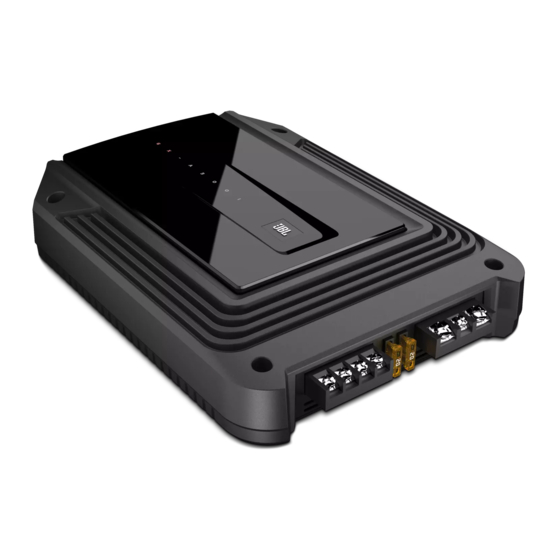
JBL GX-A604 Owner's Manual
Power amplifier
Hide thumbs
Also See for GX-A604:
- Owner's manual (470 pages) ,
- Service manual (18 pages) ,
- Features & specifications (2 pages)
Advertisement
Table of Contents
- 1 Location and Mounting
- 2 Included Items
- 3 Installation Warnings and Tips
- 4 Installation Location
- 5 Mounting the Amplifier
- 6 Power and Ground Connections
- 7 Using the Connectors
- 8 Speaker and Input Connections
- 9 Using the Speaker-Level Inputs
- 10 Set the Crossover Controls
- 11 Set the Input Level
- 12 Set the Bass Boost
- 13 Power and Protection Leds
- 14 Troubleshooting
- 15 Specifications
- Download this manual
See also:
Owner's Manual
Advertisement
Table of Contents

Related Manuals for JBL GX-A604


Summary of Contents for JBL GX-A604
- Page 1 GX-A604/GX-A602/GX-A3001 power ampliÄ er OWNER'S MANUAL...
-
Page 2: Location And Mounting
THANK YOU for purchasing a JBL ® GX-series amplifier. So we can better serve you should you require warranty service, please retain your original sales receipt and register your amplifier online at www.jbl.com. INCLUDED ITEMS Speaker-level input harness GX-Series Amplifier (x 1) -
Page 3: Installation Location
3. Drill pilot holes in the mounting surface. 4. Attach the amplifier to the mounting surface with four appropriate mounting screws of your own choice. We suggest using #8 Phillips-head sheet metal screws. Make sure the amplifier is mounted securely. www.jbl.com... -
Page 4: Power And Ground Connections
POWER AND GROUND CONNECTIONS IMPORTANT: Disconnect the vehicle's negative (–) battery terminal before beginning the installation. The GX series amplifiers are capable of delivering high power levels, and require a heavy-duty and reliable connection to the vehicle’s electrical system to achieve optimal performance. Please adhere to the following instructions carefully. USING THE CONNECTORS GX-series amplifiers use the same type of screw terminals for power and speaker connections. - Page 5 4. When you are finished routing and connecting this wire, install the appropriate >#10AWG (5.26mm ) Wire fuse in the holder you installed near the battery. (GX-A604, GX-A3001 – 50A fuse; GX-A602 – 30A fuse) Chassis Ground (bare metal) www.jbl.com...
-
Page 6: Speaker And Input Connections
IMPORTANT: Make sure the (+) and (–) bare wires do not touch each other or the other terminal at both the amplifier terminals and speaker terminals. Touching wires can cause a short circuit that can damage the amplifier. GX-A604 SPEAKER CONNECTIONS: 4-CHANNEL OPERATION Minimum speaker impedance: 2 ohms (each) •... - Page 7 GX-A604 INPUT CONNECTIONS: 4-CHANNEL OPERATION Connect your source unit or processor's front and rear left and right outputs to the amplifier's inputs as shown in the illustration. Source Unit Front Line Outputs Rear Line Outputs See Set The Crossover Controls, on page 11, for information about setting the amplifier's controls for 4-channel operation.
- Page 8 GX-A604 SPEAKER CONNECTIONS: 3-CHANNEL OPERATION Minimum speaker impedance: 2 ohms each (left & right speakers); 4 ohms (subwoofer) • Connect the left and right speakers to the FL and FR (+) and (–) terminals • Connect the subwoofer to the RL (+) and RR (–) terminals. (The rear-channel Bass Boost control makes the rear channels preferable for subwoofer connection.
- Page 9 GX-A604 INPUT CONNECTIONS: 3-CHANNEL OPERATION Connect your source unit or processor's line outputs as shown in the illustration below. Set the input mode switch in the "4CH" position NOTE: Use a "Y"-adapter to connect the source unit's subwoofer output to the amplifier's rear left and right input jacks.
- Page 10 GX-A604 SPEAKER CONNECTIONS: 2-CHANNEL OPERATION Minimum speaker impedance: 4 ohms (each) Connect the left and right speakers as shown in the illustration below. Left Speaker Right Speaker Speaker Fuses 20A...
- Page 11 GX-A604 INPUT CONNECTIONS: 2-CHANNEL OPERATION Connect your source unit or processor's line outputs as shown in the illustration below. Use only the front left and right input connections and make sure that the Input Mode switch is set in the "2CH" position.
-
Page 12: Using The Speaker-Level Inputs
USING THE SPEAKER-LEVEL INPUTS If your source unit doesn't have line-level outputs you can use the included speaker-level input harness to connect the amplifier to the source unit's speaker outputs. From left to right, the conductors are: L+, L–, R–, R+ (see the illustration to the right). - Page 13 Source Unit See Set The Crossover Controls, on page 11, for information about setting the amplifier's controls for 2-channel operation. To use the speaker level inputs instead of the line-level inputs, see Using The Speaker-Level Inputs, on page 12. www.jbl.com...
- Page 14 GX-A602 SPEAKER CONNECTIONS: BRIDGED OPERATION Bridged operation provides a single high-power channel for a subwoofer Minimum speaker impedance: 4 ohms Connect the subwoofer to the RL (+) and RR (–) terminals.) NOTE: You can connect two 2-ohm subwoofers in series to maintain the required 4-ohm impedance for bridged operation.
- Page 15 Output Source Unit See Set The Crossover Controls, on page 11, for information about setting the amplifier's controls for bridged operation. To use the speaker-level inputs instead of the line-level inputs, see Using The Speaker-Level Inputs, on page 12. www.jbl.com...
- Page 16 GX-A3001 SPEAKER CONNECTIONS Minimum speaker impedance; 2 ohms (single subwoofer); 4 ohms (2 subwoofers) The GX-A3001 has two parallel sets of speaker connectors, allowing you to connect two subwoofers. Fuses 20A +12V 4-Ohm Subwoofer 4-Ohm Subwoofer • If you are using a single subwoofer you can connect it to either set of GX-A3001 speaker connectors. •...
- Page 17 L+L–R–R+ "Y"-Adapter Subwoofer Output Source Unit See Set The Crossover Controls, on page 11, for information about setting the amplifier's controls. To use the speaker-level inputs instead of the line-level inputs, see Using The Speaker-Level Inputs, on page 6. www.jbl.com...
- Page 18 CONTROLS, INPUT CONNECTIONS AND INDICATORS GX-A604 Input Front Rear Rear Rear Power Protection Mode Speaker-Level Line-Level Level Crossover Indicator Indicator Switch Input Input Control Filter Switch Connector Connectors Rear Rear Front Bass Front Front Speaker-Level Crossover Line-Level Boost Crossover Level...
- Page 19 GX-A602 L+L–R–R+ Line-level Speaker-Level Crossover Bass Boost Protection Input Connector Filter Switch Switch Input Connectors Indicator Level Power Control Indicator GX-A3001 L+L–R–R+ Line-Level Speaker-Level Level Crossover Bass Boost Protection Input Connectors Input Connector Control Control Control Indicator Power Indicator www.jbl.com...
-
Page 20: Set The Crossover Controls
SET THE CROSSOVER CONTROLS GX-A604: 4-CHANNEL OPERATION Input Mode switch: Set the Input Mode switch in the "4CH" position. Front Crossover Filter switch: Set the Front Crossover Filter switch in the “ON” (high-pass) position. This will limit the amount of low-frequency energy sent to the speakers, significantly reducing distortion and preventing the speakers from damage. - Page 21 “hole,” where the sounds that occur between the subwoofer and other speakers seem to drop out. The illustration to the right shows the recommended Rear Crossover control frequency range. GX-A604: 2-CHANNEL OPERATION Input Mode switch: Set the Input Mode switch in the "2CH" position.
-
Page 22: Set The Input Level
3. Slowly turn the Level control on the front-channel amplifier clockwise until the music begins to sound distorted. 4. Turn the Level control counter-clockwise slightly until the music no longer sounds distorted. 5. If you're using more than one amplifier or are using the GX-A604, repeat Steps 3 – 4 for all remaining amplifier Level controls. -
Page 23: Set The Bass Boost
SET THE BASS BOOST GX-A604: When you’re using the amplifier’s rear channels to power a subwoofer, the Bass Boost switch can provide 12dB of bass boost at 45Hz. (The switch only affects the amplifier's rear channels.) Set this switch according to your personal taste, but if using it causes audible distortion or bottoming of your subwoofer we recommend setting it to "OFF."... -
Page 24: Troubleshooting
Correct all short circuits before reconnecting the speakers to the amplifier. – If the amplifier does not turn on (the Protection LED is still red and the Power LED is off), contact your authorized JBL dealer for assistance. - Page 25 • Check that the vehicle audio system's source unit's balance and fader controls are set to their connected to the amplifier center (midpoint) positions. • (GX-A604): Check that the setting of the amplifier's Mode Switch matches the input and speaker connections made to the amplifier Sound is too quiet, even with the vehicle audio •...
-
Page 26: Specifications
SPECIFICATIONS GX-A604 GX-A602 GX-A3001 Max power (15.5V, 1kHz, 10%THD, 415W (15.5V, 50Hz, 10% THD, 435W 280W total ch, 2 ohms) 2 ohms) Rated power output @ 4 ohms 60W x 4 60W x 2 200W x 1 Bridged power output... - Page 27 www.jbl.com...
- Page 28 8500 Balboa Boulevard, Northridge, CA 91329 USA © 2013 HARMAN International Industries, Incorporated. All rights reserved. JBL is a trademark of HARMAN International Industries, Incorporated, registered in the United States and/or other countries. All Rights Reserved. Features, specifications and appearance are subject to change without notice.