JBL GX-A604 Service Manual
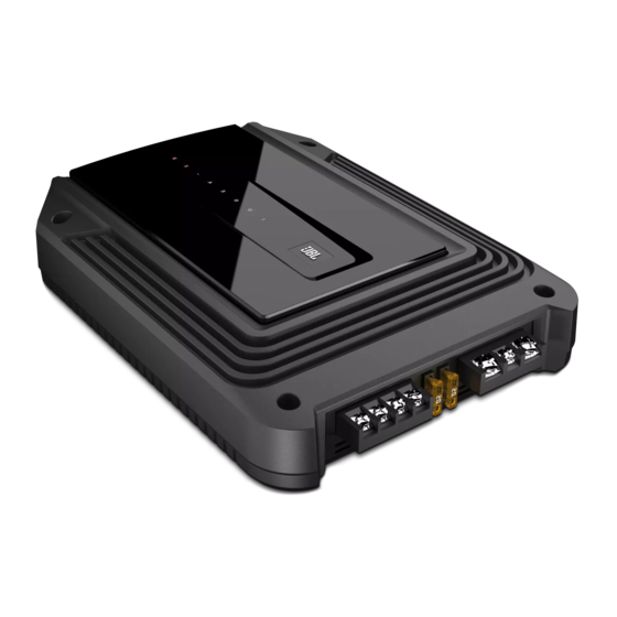
435-watt full range 4-channel car power amplifier
Hide thumbs
Also See for GX-A604:
- Owner's manual (470 pages) ,
- Features & specifications (2 pages) ,
- Service manual (20 pages)
Table of Contents
Advertisement
Quick Links
GX-A604
435-Watt full range 4-channel car power amplifier
OWNER'S MANUAL
TROUBLESHOOTING
TECHNICAL SPECIFICATIONS
Released EU2015
CONTENTS
PACKING LIST
2
BLOCK DIAGRAM
9
SCHEMATIC DIAGRAMS
11
Harman Consumer Group, Inc.
8500 Balboa Boulevard
Northridge, California 91329
Service Manual
Rev 0, 00/20XX
12
13
14
Advertisement
Table of Contents

Related Manuals for JBL GX-A604


Summary of Contents for JBL GX-A604
- Page 1 Service Manual GX-A604 435-Watt full range 4-channel car power amplifier CONTENTS PACKING LIST OWNER’S MANUAL BLOCK DIAGRAM TROUBLESHOOTING SCHEMATIC DIAGRAMS TECHNICAL SPECIFICATIONS Released EU2015 Harman Consumer Group, Inc. Rev 0, 00/20XX 8500 Balboa Boulevard Northridge, California 91329...
-
Page 2: Power Connectors
(12 V) connectIon Audio System Head Unit 1. C onnect a wire (minimum 10 AWG – 5.3 mm Remote Turn-On directly to the battery’s positive (+) terminal. (optional) 2. I nstall a fuse holder for a 50 A fuse (GX-A604, >#18 AWG (0.82 mm ) Wire GX-A3001) or a 30 A fuse (GX-A602) on this wire within 18" (46 cm) of the battery’s (+) terminal. Do not install the fuse in the holder at this time. - Page 3 And input connections Always connect the (+) speaker terminal on the amplifier to the (+) terminal on the speaker and the (–) speaker terminal on the amplifier to the (–) terminal on the speaker. IMPORTANT: Make sure the (+) and (–) bare wires do not touch each other or the other terminal at both the amplifier terminals and speaker terminals. Touching wires can cause a short circuit that can damage the amplifier. gX-a604 speaker connectIons: 4-channel operatIon Minimum speaker impedance: 2 ohms (each) • Connect the front speakers to the FL and FR (+) and (–) terminals. • Connect the rear speakers to the RL and RR (+) and (–) terminals. Front Right Speaker...
-
Page 4: Source Unit
Input connectIons: 4-channel operatIon Connect your source unit or processor’s front and rear left and right outputs to the amplifier’s inputs as shown in the illustration. Source Unit Front Line Outputs Rear Line Outputs See Set The Crossover Controls, on page 20, for information about setting the amplifier’s controls for 4-channel operation. To use the speaker-level inputs instead of the line-level inputs, see Using The Speaker-Level Inputs, on page 12. www.jbl.com... - Page 5 3-channel operatIon Minimum speaker impedance: 2 ohms each (left & right speakers); 4 ohms (subwoofer) • Connect the left and right speakers to the FL and FR (+) and (–) terminals • C onnect the subwoofer to the RL (+) and RR (–) terminals. (The rear-channel Bass Boost control makes the rear channels preferable for subwoofer connection. See Set The Bass Boost, on page 23.) NOTE: You can connect two 2-ohm subwoofers in series to maintain the required 4-ohm mimimum impedance for the subwoofer channel.
- Page 6 Input connectIons: 3-channel operatIon Connect your source unit or processor’s line outputs as shown in the illustration below. Set the input mode switch in the "4CH" position NOTE: Use a "Y"-adapter to connect the source unit’s subwoofer output to the amplifier’s rear left and right input jacks. "Y"-Adapter Source Unit Front Line Outputs Subwoofer Line Output See Set The Crossover Controls, on page 20, for information about setting the amplifier’s controls for 3-channel operation. To use the speaker-level inputs instead of the line-level inputs, see Using The Speaker-Level Inputs, on page 12.
-
Page 7: Left Speaker
2-channel operatIon Minimum speaker impedance: 4 ohms (each) Connect the left and right speakers as shown in the illustration below. Left Speaker Right Speaker Speaker Fuses 20A... - Page 8 Input connectIons: 2-channel operatIon Connect your source unit or processor’s line outputs as shown in the illustration below. Use only the front left and right input connections and make sure that the Input Mode switch is set in the "2CH" position. Source Unit Front Line Outputs See Set The Crossover Controls, on page 20, for information about setting the amplifier’s controls for 2-channel operation. To use the speaker-level inputs instead of the line-level inputs, see Using The Speaker-Level Inputs, on page 12. www.jbl.com...
-
Page 9: Troubleshooting
• C onfirm that the vehicle’s electrical system is supplying between 9 V and 16 V DC to the amplifier. If the supply voltage is outside of this range, correct the condition before attempting to use the amplifier. • If the amplifier has overheated, wait until it has cooled down before attempting to use it again. • Disconnect all speakers from the amplifier and attempt to turn it on again: – I f the amplifier turns on (the Power LED is orange), there is a short circuit in one or more of the speaker wires. Correct all short circuits before reconnecting the speakers to the amplifier. – I f the amplifier does not turn on (the Protection LED is still red and the Power LED is off), contact your authorized JBL dealer for assistance. - Page 10 Sound only comes from some of the speakers • C heck that the vehicle audio system’s source unit’s balance and fader controls are set to their connected to the amplifier center (midpoint) positions. • ( GX-A604): Check that the setting of the amplifier’s Mode Switch matches the input and speaker connections made to the amplifier Sound is too quiet, even with the vehicle audio • C heck that the amplifier’s Level controls are not turned too low. See Set The Input Level, on system’s source unit volume all the way up...
-
Page 11: Specifications
GX-A604 GX-A602 GX-A3001 Max power (15.5 V, 1 kHz, 10% THD, 415W (15.5 V, 50 Hz, 10% THD, 435 W 280 W total ch, 2 ohms) 2 ohms) Rated power output @ 4 ohms 60 W x 4 60 W x 2 200 W x 1 Bridged power output 170 W x 2 170 W x 1 (4 ohms, 1% THD) THD+N at rated power <1% <1% <1% Signal-to-noise (2 V @ 4 ohms) >75 dB >75 dB >75 dB Effective damping factor (4 ohms) >50... - Page 12 GX-A604 packing list...
- Page 13 HP/LP pass variable crossover bass boost crossover INPUT SENS 0.2V-4V FLAT 10Hz 32Hz 320Hz > 40 KHz 4ch(R) input input selector 32/320Hz 12dB/ oct 45Hz 0-12dB 4 ch(R) +out 2Ω/4Ω HI-IN auto ON GROUND power supply +12V power FUSE GX-A604...
- Page 14 10uF/50V 10uF/50V R18F R19F FR 4CH 5.1K 2.2K FR-H FR+H FR+HI BA4560 4.7K 10U/50V 10uF/50V R15B 10U/50V R11F C13F 100P 4.3K 10uF/50V 100uF/25V NP 10uF/25V NP 100uF/16V Hi auto SW1C VR1A 010703000103 SW2C 110103000040 110103000040 C25B 100P R16B 910R GX-A604...
- Page 15 R137 R136 15 15 15 15 15 C133 Q105 R139 Q104 2SA1015 R157 2SA1015 C132 680R 100P R168 R144 122P R158 D102 4R7/0.25W 1N4148 Q107 Q112 C158 Q110 R160 B688 2N5551 2SB649 C132A 100P R170 R149 C137 47uF/25V -VCC GX-A604...
- Page 16 R358 D302 1N4148 2SC1815 4R7/0.25W R368 4148 PROT 1N4148 R23A 122P Q307 2N5551 84.5K R360 C358 Q312 FL+out Q310 B688 R24A 2SB649 FR-out 6.2K 84.5K R370 C332A 2SC1815 R349 C337 RL+out 84.5K 100P 47uF/25V RR-out 84.5K -VCC 6.8K 220U/25V GX-A604...
- Page 17 -15V +15V 104P 4.7R 030123000121 R10P 104P P+12V 220K U2PA +BATT 4558 R11P 4.7R 120903000120 -AMP -AMP U2PB +12V 4558 R16P 2.2K 2SC1815 2C22 PGND C152 4.7R 104P +15V C122 104P +AMP +AMP PC817 J168 J169 J170 J171 104P 105/25V 4.7uF/50V 1N4001 R148P...
- Page 18 R53C C50C C52C C53C R64C R63C 823P C51C 470K R51C 470K 333P 104P J175 -15V 470R R60C 4.7R R52C R50C R55C SW3A VR4A 9.1K 110103000062 9.1K LP RL R57C C100K VR4B R62C 7.5K TL074 C100K FULL RL PTC3 TL074 104P 080513000014 TL074 RL+SG...
Need help?
Do you have a question about the GX-A604 and is the answer not in the manual?
Questions and answers