Table of Contents
Advertisement
Quick Links
Advertisement
Table of Contents

Related Manuals for Asus S1016P


Summary of Contents for Asus S1016P
- Page 1 S1016P 1U Rackmount Server User Guide...
- Page 2 ASUSTeK COMPUTER INC. (“ASUS”). ASUS provides this manual “as is” without warranty of any kind, either express or implied, including but not limited to the implied warranties or conditions of merchantability or fitness for a particular purpose. In no...
-
Page 3: Table Of Contents
Contents Notices ........................vii REACH ......................vii Safety information ....................viii Australia statement notice ................ix About this guide ......................x Chapter 1: Product Introduction System package contents ................. 1-2 Serial number label ..................1-3 System specifications ................1-4 Front panel features ................... 1-6 Rear panel features .................. - Page 4 Internal connectors ..................4-9 Onboard LEDs ..................4-19 Chapter 5: BIOS setup Managing and updating your BIOS ............5-2 5.1.1 ASUS CrashFree BIOS 3 utility........... 5-2 5.1.2 ASUS EzFlash Utility..............5-3 5.1.3 BUPDATER utility ............... 5-4 BIOS setup program .................. 5-6 5.2.1...
- Page 5 Contents 5.4.11 Intel Server Platform Services ........... 5-23 5.4.12 Onboard LAN Configuration ............5-23 5.4.13 Serial Port Console Redirection ..........5-24 5.4.14 Runtime Error Logging Support ..........5-26 5.4.15 APM ..................5-26 5.4.16 Onboard LAN BCM57840S Configuration ........ 5-27 5.4.17 Network Stack ................
- Page 6 Installing the VGA driver ................. 7-28 ® Installing the Intel C22x MEI NULL HECI driver ........7-31 ® Installing the Intel I210 Gigabit Adapter driver ........7-33 Installing the Broadcom 10G driver ............7-37 Appendix A: Reference Information ASUS contact information ..................A-2...
-
Page 7: Notices
Radio Interference Regulations of the Canadian Department of Communications. This Class A digital apparatus complies with Canadian ICES-003. REACH Complying with the REACH (Registration, Evaluation, Authorization, and Restriction of Chemicals) regulatory framework, we publish the chemical substances in our products at ASUS REACH website at http://csr.asus.com/english/REACH.htm. -
Page 8: Safety Information
Safety information Electrical Safety • Before installing or removing signal cables, ensure that the power cables for the system unit and all attached devices are unplugged. • To prevent electrical shock hazard, disconnect the power cable from the electrical outlet before relocating the system. -
Page 9: Australia Statement Notice
If you require assistance please call ASUS Customer Service 1300 2787 88 or visit us at http://support.asus.com... -
Page 10: About This Guide
About this guide Audience This user guide is intended for system integrators, and experienced users with at least basic knowledge of configuring a server. Contents This guide contains the following parts: Chapter 1: Product introduction This chapter describes the general features of the server, including sections on front panel and rear panel specifications. - Page 11 Refer to the following sources for additional information, and for product and software updates. ASUS Server Web-based Management (ASWM) user guide This manual tells how to set up and use the proprietary ASUS server management utility. ASUS websites The ASUS websites worldwide provide updated information for all ASUS hardware and...
-
Page 13: Chapter 1: Product Introduction
Chapter 1: Product Introduction Product introduction This chapter describes the general features of the chassis kit. It includes sections on front panel and rear panel specifications. -
Page 14: System Package Contents
1 x Rail Kit (with Cable Arm) Optional Item 1 x CPU heatsink 1 x ASUS ASMB7-iKVM Remote management card *ASUS System Web-based Management If any of the above items is damaged or missing, contact your retailer. Chapter 1: Product introduction... -
Page 15: Serial Number Label
Please take note of the product’s serial number. The Serial number contains 14 characters such as xxS0xxxxxxxxxx similar to the figure shown below. You need to provide the correct serial number to the ASUS Technical Support team member if you need assistance or, when requesting support. -
Page 16: System Specifications
System specifications The ASUS S1016P is a 1U barebone server system featuring the ® ® ASUS P9D-MH/SAS/10G-DUAL Server Board. The server supports Intel LGA1150 Intel ® Xeon E3-1200 Processor v3 plus other latest technologies through the chipsets onboard. Model Name... - Page 17 Rating: 100-127 Vac / 200-240 Vac, 7.1A / 3.4A, 47-63Hz, Class I Operating temperature: 10 C – 35 Environment Non operating temperature: -40 C – 70 Non operating humidity: 20% – 90% (Non condensing) Specifications are subject to change without notice. ASUS S1016P...
-
Page 18: Front Panel Features
Front panel features The front panel of the S1016P features a simple yet compact design with the HDD LEDs, USB 2.0 ports, Reset button, and the Power buttons all conveniently located at the front panel for easy access. Refer to the Front panel LEDs section for the LED descriptions. -
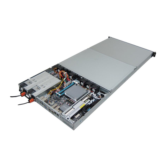
Page 19: Internal Features
The barebone server does not include a floppy disk drive. Connect a USB floppy disk drive to any of the USB ports on the front or rear panel if you need to use a floppy disk. *WARNING HAZARDOUS MOVING PARTS KEEP FINGERS AND OTHER BODY PARTS AWAY ASUS S1016P... -
Page 20: Led Information
LED information 1.7.1 Front panel LEDs HDD location and LED information The following illustration shows the HDD location on the server system and its equivalent LED number of the server system's front panel. Chapter 1: Product introduction... -
Page 21: Led Indications
SFP+_LED2 No activity. Red Bright HDD fail HDD Status RAID re-building activity Blinking Green Bright HDD power HDD Active Green HDD RAID re-building Blinking HDD active Green Read/write data from/into SAS/ SATA HDD Blinking HDD Access No activity. ASUS S1016P... -
Page 22: Lan (Rj-45) Leds
1.7.2 LAN (RJ-45) LEDs SPEED LED ACT/LINK LED ACT/LINK LED SPEED LED Status Description Status Description No link 10 Mbps connection GREEN Linked ORANGE 100 Mbps connection BLINKING Data activity GREEN 1 Gbps connection 1.7.3 10G LAN port LEDs ACTIVITY LED SPEED LED 10G LAN port 1 LEDs 10G LAN port 2 LEDs... -
Page 23: Chapter 2: Hardware Information
Chapter 2: Hardware Information Hardware Information This chapter lists the hardware setup procedures that you have to perform when installing or removing system components. -
Page 24: Chassis Cover
Chassis cover To remove the chassis cover: Release the two (2) screws on the sides of the chassis. Release the thumbscrew on the rear of the chassis. Slide the chassis cover towards the rear to disengage it from the chassis. Lift the chassis cover to completely remove it from the chassis. -
Page 25: Hdd Compartment
Press the side locks located on the side of the server chassis. Slowly lift the cover. Ensure that the side latch is locked in place. To close the HDD compartment, slowly pull in the cover until it locks into place. ASUS S1016P... -
Page 26: Central Processing Unit (Cpu)
Contact your retailer immediately if the PnP cap is missing, or if you see any damage to the PnP cap/socket contacts/motherboard components. ASUS shoulders the repair cost only if the damage is shipment/transit- related. - Page 27 CPU notches to the socket's alignment CPU notches keys. The CPU fits in only one orientation. DO Gold NOT force the CPU into the socket to triangle Alignment prevent bending the pins on the socket mark and damaging the CPU. Alignment ASUS S1016P...
- Page 28 Close the load plate (A), ensuring that the front edge of the load plate slides Load lever under the retention lock (B) then push down the load lever (C). Retention lock Insert the load lever under the retention tab to remove the PnP cap from the CPU socket.
-
Page 29: Installing The Cpu Heatsink
Tighten the four heatsink screws in a criss-cross sequence. Place the airduct cover on top of the heatsink and CPU assembly. Ensure that the airduct cover is fitted securely in place. ASUS S1016P... - Page 30 Secure the airduct cover to the motherboard with a screw. Chapter 2: Hardware setup...
-
Page 31: System Memory
1333/1600 Dual Rank • Always install DIMMs with the same CAS latency. For optimum compatibility, it is recommended that you obtain memory modules from the same vendor. • Start installing the DIMMs in slots A2 and B2 (Blue). ASUS S1016P... -
Page 32: Installing A Dimm
2.4.3 Installing a DIMM Unlock a DIMM socket by pressing the DIMM notch retaining clip outward. Align a DIMM on the socket such that the notch on the DIMM matches the DIMM slot key on the socket. DIMM slot key Unlocked retaining clip A DIMM is keyed with a notch so that it fits in only one direction. -
Page 33: Hard Disk Drives (Hdds)
Match the four (4) notches on the tray to the screw latches of the SAS/SATA HDD (A) then lift the HDD tray bracket (B). Ensure that the location of the SAS/SATA connectors is oriented as shown: handle SAS/SATA connector HDD and HDD tray handle bracket asssembly SAS/SATA connector HDD tray bracket ASUS S1016P 2-11... - Page 34 (optional) Secure the SAS/SATA HDD and HDD tray bracket assembly using the bundled set of screws. SAS/SATA handle connector Ensure that the HDD is securely attached to the HDD tray. Place the SAS/SATA HDD and HDD tray assembly into the HDD bay. •...
- Page 35 Push down the HDD tray handle until the SAS/SATA HDD and HDD tray assembly locks in place. Ensure that the SAS/SATA HDD and HDD tray assembly is seated securely in place. Check the status of the LEDs at the front panel on the particular drive you just installed. ASUS S1016P 2-13...
- Page 36 Replacing HDD Be extra careful when performing the steps. Do not drop the hard disk drives. Lift the HDD tray handle to a 90° angle to disengage the drive from the bay. Take out the SAS/SATA HDD and HDD tray assembly. 2-14 Chapter 2: Hardware setup...
- Page 37 Attach the SAS/SATA HDD into the HDD tray by matching and inserting the four (4) studs of the tray to the screw holes of the HDD. Orient the location of the SAS/SATA connectors as shown: screw holes on the HDD studs of the HDD tray ASUS S1016P 2-15...
- Page 38 Lift the SAS/SATA HDD and HDD tray assembly using the handle then place it into the HDD bay. Ensure that the SAS/SATA connector of the SAS/SATA HDD is aligned towards the SATA connector onboard and the four (4) notches on the HDD tray matches the four (4) contours on the drive bay.
-
Page 39: Cable Connections
SATA conectors (system default; from motherboard to SATA/SAS backplane) System auxiliary panel connector (from motherboard to front I/O board) System panel connector (from motherboard to front I/O board) SAS connectors (from motherboard to SATA/SAS backplane) Serial General Purpose Input/Output connectors ASUS S1016P 2-17... -
Page 40: Replaceable Components
Replaceable components Ensure that the system is turned off before removing any components. 2.7.1 System fans To uninstall the system fans: Disconnect the system fan cable from the fan connector on the motherboard. Lift the fan and set aside. Repeat steps 1—2 to remove the other fans. To reinstall the system fans: Align and insert the fan into the fan slot. - Page 41 Ensure that the rubber anchors are fitted neatly on the fan slot notches. Connect the system fan cable into the fan connector. Rubber anchors Rubber anchors Repeat steps 1-2 to install the other fans. ASUS S1016P 2-19...
-
Page 42: Optional Components
Optional components The following optional components allows for easy repair or component replacement when necessary. • ASMB7-iKVM card Ensure that the system is turned off before removing any components. 2.8.1 Installing ASMB7 series management board Follow the steps below to install an optional ASMB7 series management board on your motherboard. -
Page 43: Chapter 3: Installation Options
Chapter 3: Installation Options Installation Options This chapter describes how to install the optional components and devices into the barebone server. -
Page 44: Rail Kit And Server Installation
Rail kit and server installation Refer to the installation guide of the rail kit (including the cable arm) in installing the rail kit to the server. • Ensure that the rack rail cabinet and the rack posts are stable and standing firmly on a level surface. -
Page 45: Chapter 4: Motherboard Info
Chapter 4: Motherboard Info Motherboard Info This chapter includes the motherboard layout and brief descriptions of the jumpers and internal connectors. -
Page 46: Motherboard Layout
Motherboard layout Layout contents Jumpers Page 1. Clear RTC RAM (CLRTC1) 2. VGA controller setting (3-pin VGA_SW1) 3. LAN controller setting (3-pin LAN_SW1, LAN_SW2) 4. RAID configuration utility selection (3-pin RAID_SEL1) 5. SFP+12_LED connectors (5-pin LAN34_LED1) 6. VGA connector (16-pin VGA_HDR1) 7. Broadcom 10GbE controller setting (3-pin BCM10G_SW1) 8. LSI 2308 SAS/SATA RAID controller setting (3 pin SAS_SW1) Chapter 4: Motherboard information... - Page 47 13. SATA DOM power connector (4-pin PWR3) 4-16 14. ATX power connectors (24-pin EATXPWR1, 8-pin EATX12V1) 4-17 15. System panel connector (20-1 pin PANEL1) 4-18 16. Auxiliary panel connector (20-2 pin AUX_PANEL1) 4-19 Onboard LEDs Page 1. Standby Power LED (SB_PWR1) 4-20 2. Baseboard Management Controller LED (BMC_LED1) 4-20 3. CPU Warning LED (ERR_CPU1) 4-21 4. Power LED (+5V_LED) 4-21 5. Location LED (LOC_LED1) 4-22 6. RLED (RLED1) 4-22 7. PCIE Link LED (PCIE_LINKUP1) 4-23 8. Data Layer LED (DL_ACTIVE1) 4-23 ASUS S1016P...
-
Page 48: Jumpers
Jumpers Clear RTC RAM (3-pin CLRTC1) This jumper allows you to clear the Real Time Clock (RTC) RAM in CMOS. You can clear the CMOS memory of date, time, and system setup parameters by erasing the CMOS RTC RAM data. The onboard button cell battery powers the RAM data in CMOS, which include system setup information such as system passwords. - Page 49 1–2 to activate the VGA feature. LAN controller setting (3-pin LAN_SW1, LAN_SW2) These jumpers allow you to enable or disable the onboard Intel I210AT Gigabit LAN ® controllers. Set to pins 1-2 to activate the Gigabit LAN feature. ASUS S1016P...
- Page 50 RAID configuration utility selection (3-pin RAID_SEL1) This jumper allows you to select the RAID configuration utility to use when you ® create disk arrays. Place the jumper caps to pins 2–3 to use the Intel Rapid Storage Technology. SFP+12 LED connectors (5-1 pin LAN34_LED1) These leads are for 10Gb LAN activity LEDs on the front panel. Connect the LAN LED cable to the backplane for LAN activity indication. Chapter 4: Motherboard information...
- Page 51 Set to pins 1-2 to enable, otherwise set to pins 2-3 to disable the Broadcom 10Gb chip. ASUS S1016P...
- Page 52 LSI 2308 SAS/SATA RAID controller setting (3 pin SAS_SW1) This jumper allows you enable or disable the LSI 2308 SAS/SATA RAID controller. Set to pin 1-2 to enable, otherwise set to pin 2-3 to disable the LSI 2308 SAS/SATA RAID controller.
-
Page 53: Internal Connectors
Serial ATA hard disk drives that allows up to 6Gbps of data transfer rate. If you installed Serial ATA hard disk drives, you can create a RAID 0, RAID 1, RAID 10, or RAID 5 configuration. The actual data transfer rate depends on the speed of Serial ATA hard disks installed. ASUS S1016P... - Page 54 SAS connectors (7-pin SAS connector [Light Blue]) Supported by the LSI 2308 SAS/SATA RAID controller, these connectors are for the Serial ATA signal cables for Serial ATA hard disk drives that allows up to 6Gbps of data transfer rate. If you installed Serial ATA hard disk drives, you can create a RAID 0, RAID 1, RAID 10, or RAID 1E configuration.
- Page 55 This connector allows you to connect a Thermal sensor cable that is used for temperature monitoring. Connect the Thermal sensor cable to the connector and place its probe to the device that you want to check the temperature. ASUS S1016P 4-11...
- Page 56 • These are not jumpers! DO NOT place jumper caps on the fan connectors! • All fans feature the ASUS Smart Fan technology. Serial port connectors (10-1 pin COM1) These connectors are for the serial COM ports. Connect the serial port module cable to one of these connectors, then install the module to a slot opening at the back of the system chassis.
- Page 57 The SGPIO 1 connector is used for the Intel Rapid Storage Technology Enterprise SGPIO interface that controls the LED pattern generation, device information, and general purpose data. Serial General Purpose Input/Output connectors (8-1 pin SGPIO2, SGPIO3) The SGPIO 2 and SGPIO 3 connectors are for the LSI 2308 RAID controller. ASUS S1016P 4-13...
- Page 58 This connector allows you to connect SMBus (System Management Bus) to the power supply unit to read PSU information. Devices communicate with an SMBus host and/or other SMBus devices using the SMBus interface. This connector functions only when you install the ASUS ASMB7. Hard disk activity connector (4-pin HDLED1) This LED connector is for the storage add-on card cable connected to the SATA or SAS add-on card.
- Page 59 This 4-pin connector is for 5V power of a certain SATA DOM (Disk on Module) device when using an appropriate cable. • The SATA DOM power connector is for output power only. It has a maximum output current of 1A. • Ensure that the power of the SATA DOM device that you will use is less than 1A. ASUS S1016P 4-15...
- Page 60 ATX power connectors (24-pin EATXPWR1, 8-pin EATX12V1) These connectors are for the ATX power supply plugs. The power supply plugs are designed to fit these connectors in only one orientation. Find the proper orientation and push down firmly until the connectors completely fit. • DO NOT forget to connect the 24-pin, the 8-pin power plugs, and the 4-pin PWR3; otherwise, the system will not boot up. •...
- Page 61 Pressing the power switch for more than four seconds while the system is ON turns the system OFF. Reset button (2-pin RESET) This 2-pin connector is for the chassis-mounted reset button for system reboot without turning off the system power. ASUS S1016P 4-17...
- Page 62 Auxiliary panel connector (20-2 pin AUX_PANEL1) This connector is for additional front panel features including front panel SMB, locator LED and switch, chassis intrusion, and LAN LEDs. Front panel SMB (6-1 pin FPSMB) These leads connect the front panel SMBus cable. LAN activity LED (2-pin LAN1LINK and 2-pin LAN2LINK) These leads are for Gigabit LAN activity LEDs on the front panel.
-
Page 63: Onboard Leds
This is a reminder that you should shut down the system and unplug the power cable before removing or plugging in any motherboard component. The illustration below shows the location of the onboard LED. Baseboard Management Controller LED (BMC_LED1) The green heartbeat LED blinks per second to indicate that the ASMB7 is working normally. The heartbeat LED functions only when you install the ASUS ASMB7 Management card ASUS S1016P 4-19... - Page 64 CPU Warning LED (ERR_CPU1) The CPU warning LED lights up to indicate that a CPU error or failure has occurred. Power LED (+5V_LED1) This LED lights up when the Power-on button is pressed and the system is on. Chapter 4: Motherboard information 4-20...
- Page 65 Location LED (LOCLED1) The Location LED is an onboard LED that ligths up when the Location Button on the front panel is pressed. This LED helps you visually locate the server among other servers especially when you are located at the back of the server rack. RLED (RLED1) This LED lights up to indicate that the LSI 2308 is working properly. If the LED is unlit, the LSI 2308 is either in fault state or a problem have occurred. ASUS S1016P 4-21...
- Page 66 PCIE LINK Status LED (PCIE_LINKUP1) This LED is for the PCIE link status of the Broadcom 10GbE chip. The unlit LED indicates the PCIE link status is not established and green LED indicates activity or operational condition. Data Layer LED (DL_ACTIVE1) This LED is for the data layer link status of the Broadcom 10GbE chip. If unlit, the Broadcom 10GbE chip is either in fault state or a problem have occured. Chapter 4: Motherboard information 4-22...
-
Page 67: Chapter 5: Bios Setup
Chapter 5: BIOS setup BIOS setup This chapter tells how to change the system settings through the BIOS Setup menus. Detailed descriptions of the BIOS parameters are also provided. -
Page 68: Managing And Updating Your Bios
DO NOT shut down or reset the system while recovering the BIOS! Doing so would cause system boot failure! The recovered BIOS may not be the latest BIOS version for this motherboard. Visit the ASUS website at www.asus.com to download the latest BIOS file. Chapter 5: BIOS setup... -
Page 69: Asus Ezflash Utility
To update the BIOS using EzFlash Utility: Insert the USB flash disk that contains the latest BIOS file to the USB port. Enter the BIOS setup program. Go to the Tool menu to select ASUS EzFlash Utility and press <Enter> to enable it. ASUS Tek. EzFlash Utility New Platform... -
Page 70: Bupdater Utility
The BUPDATER utility allows you to update the BIOS file in DOS environment using a bootable USB flash disk drive with the updated BIOS file. Updating the BIOS file To update the BIOS file using the BUPDATER utility: Visit the ASUS website at www.asus.com and download the latest BIOS file for the motherboard. Save the BIOS file to a bootable USB flash disk drive. Download the BUPDATER utility (BUPDATER.exe) from the ASUS support website at support.asus.com to the bootable USB flash disk drive you created earlier. Boot the system in DOS mode, then at the prompt, type: BUPDATER /i[filename].CAP... - Page 71 The utility verifies the file, then starts updating the BIOS file. ASUS Tek. EzFlash Utility New Platform Current Platform Platform : P9D-MH Platform : P9D-MH Version : 0606 Version : 0401 Build Date :03/27/2014 Build Date :09/05/2013 Start programming the Flash. DO NOT SHUTDOWN THE SYSTEM!!! Write 25%vv DO NOT shut down or reset the system while updating the BIOS to prevent system boot failure! The utility returns to the DOS prompt after the BIOS update process is completed.
-
Page 72: Bios Setup Program
Press <F5> and select Yes to load the BIOS default settings. • The BIOS setup screens shown in this section are for reference purposes only, and may not exactly match what you see on your screen. • Visit the ASUS website (www.asus.com) to download the latest BIOS file for this motherboard. Chapter 5: BIOS setup... -
Page 73: Bios Menu Screen
For changing the event log settings Boot For changing the system boot configuration Monitor For displaying the system temperature, power status, and changing the fan settings Security For changing the security settings Tool For configuring options for special functions Exit For selecting the exit options To select an item on the menu bar, press the right or left arrow key on the keyboard until the desired item is highlighted. ASUS S1016P... -
Page 74: Menu Items
5.2.3 Menu items The highlighted item on the menu bar displays the specific items for that menu. For example, selecting Main shows the Main menu items. The other items (Advanced, Event Logs, Boot, Monitor, Security, Tool, and Exit) on the menu bar have their respective menu items. 5.2.4 Submenu items A solid triangle before each item on any menu screen means that the item has a submenu. To display the submenu, select the item and press <Enter>. -
Page 75: Main Menu
= day (numeric value) yyyy = year (numeric value) 5.3.2 System Time Allows you to set the system time to [hh/mm/ss]. Where: hh = hour (numeric value) mm = minutes (numeric value) ss = seconds (numeric value) ASUS S1016P... -
Page 76: Advanced Menu
Advanced menu The Advanced menu items allow you to change the settings for the CPU and other system devices. Take caution when changing the settings of the Advanced menu items. Incorrect field values can cause the system to malfunction. Aptio Setup Utility - Copyright (C) 2013 American Megatrends, Inc. Aptio Setup Utility - Copyright (C) 2013 American Megatrends, Inc. Main Advanced Event Logs... -
Page 77: Cpu Configuration
C1 state auto undemotion [Enabled] C3 state auto demotion [Enabled] C state Pre-Wake [Enabled] CFG lock [Enabled] Package C State limit [C3] LakeTiny Feature [Disabled] Intel TXT (LT) Support [Disabled] Version 2.15.1236. Copyright (C) 2013 American Megatrends, Inc. ASUS S1016P 5-11... - Page 78 Overclocking lock [Disabled] Allows you to enable or disable the overclocking lock. Configuration options: [Enabled] [Disabled] Active Processor Cores [All] Allows you to choose the number of CPU cores to activate in each processor package. Configuration options: [All] [1] [2] [3] Execute Disable Bit [Enabled] Allows you to enable or disable the XD feature that can prevent certain classes of malicious buffer overflow attacks when combined with a supporting OS. Configuration options: [Enabled] [Disabled] Intel Virtualization Technology [Enabled] Allows you to utilize the additional hardware capabilities provided by Vanderpool Technology. Configuration options: [Enabled] [Disabled] Hardware Prefetcher [Enabled] Allows you to enable or disable the Mid Level Cache (L2) streamer. Configuration options:...
- Page 79 Allows you to enable or disable the demotion of the C6/C7 request to C3 based on uncore auto-demote information. Configuration options: [Disabled] [Enabled] Package C State limit [AUTO] Allows you set the Package C State limit to AUTO. Configuration options: [C0/C1] [C2] [C3] C6] [C7] [C7s] [AUTO] LakeTiny Feature [Disabled] Allows you enable or disable LakeTiny for C state configuration. Configuration options: [Disabled] [Enabled] Intel TXT (LT) Suppot [Disabled] Allows you to enable or disable the Intel TXT (LT) support. Configuration options: [Disabled] [Enabled] ACPI T State [Disabled] Allows you to enable or disable the ACPI T state. Configuration options: [Disabled] [Enabled] ASUS S1016P 5-13...
-
Page 80: Pch-Io Configuration
5.4.2 PCH-IO Configuration Allows you to configure PCH parameters. Aptio Setup Utility - Copyright (C) 2013 American Megatrends, Inc. Advanced USB Configuration Intel PCH RC Version 1.0.0.0 settings. Intel PCH SKU Name C224 Intel PCH Rev ID 04/C1 USB Configuration USB Configuration Allows you to set the USB Configuration settings. Aptio Setup Utility - Copyright (C) 2013 American Megatrends, Inc. Advanced USB Configuration settings USB Configuration... -
Page 81: Sata Configuration
Serial ATA Port 2 HardDisk (250.0GB) Software Preserve SUPPORTED Port 2 [Enabled] SATA Device Type [Hard Disk Driver] Spin Up Device [Disabled] SATA Controller(s) [Enabled] This allows you to enable or disable the SATA Device. Configuration options: [Enabled] [Disabled] SATA Mode Selection [AHCI] This allows you to choose how SATA controller(s) should operate. Configuration options: [AHCI] [IDE] [RAID] S.M.A.R.T. Status Check [Enabled] Self-Monitoring, Analysis, and Reporting Technology (S.M.A.R.T.) is a monitor system. When read/write of your hard disk errors occur, this feature allows the hard disk to report warning messages during the POST. Configuration options: [Enabled] [Disabled] ASUS S1016P 5-15... -
Page 82: System Agent (Sa) Configuration
Serial SATA Port 4 HardDisk (250.0GB) Software Preserve SUPPORTED Serial SATA Port 5 ASUS DVD-E8 ATAPI Software Preserve SUPPORTED 5.4.4 System Agent (SA) Configuration This allows you to change System Agent parameters. Aptio Setup Utility - Copyright (C) 2013 American Megatrends, Inc. - Page 83 Active to Precharge (tRASmin) Memory Frequency Limiter [Auto] Memory Scrambler [Enabled] Memory Remap [Enabled] GDXC Support [Disabled] Memory Frequency Limiter [Auto] This allows you to set the memory frequency in MHz. Configuration options: [Auto] [1333] [1600] Memory Scrambler [Enabled] This allows you to enable or disable the Memory Scrambler support. Configuration options: [Enabled] [Disabled] Memory Remap [Enabled] This allows you to enable or disable the Memory Remap above 4G. Configuration options: [Enabled] [Disabled] GDXC Support [Disabled] This allows you to enable or disable the GDXC feature. Configuration options: [Enabled] [Disabled] ASUS S1016P 5-17...
-
Page 84: Pci Subsystem Settings
5.4.5 PCI Subsystem Settings Allows you to configure PCI, PCI-X, and PCI Express Settings. Aptio Setup Utility - Copyright (C) 2013 American Megatrends, Inc. Advanced Change PCI Express PCI Bus Driver Version V 2.05.02 Devices Settings. PCI 64bit Resources Handling Above 4G Decoding [Disabled] PCI Common Settings Load RT32 Image [Enabled] PCI Express Settings PCIE Slot Configuration... - Page 85 Advanced Enabled/Disabled PCIE3 PCIE Slot Configuration Option Rom PCIE4 Not Present PCIE4 Option Rom [Enabled] PCIE5 Not Present PCIE5 Option Rom [Enabled] PCIE6 Not Present PCIE6 Option Rom [Enabled] PCIE Option Rom 4 - 6 [Enabled] Allows you to enable or disable the PCIE slots. Configuration Options: [Disabled][Enabled] ASUS S1016P 5-19...
-
Page 86: Usb Configuration
5.4.6 USB Configuration This allows you to make changes on the configuration settings of the USB. Aptio Setup Utility - Copyright (C) 2013 American Megatrends, Inc. Advanced USB Configuration Enables Legacy USB support. AUTO option USB Devices disables legacy 1 Mouse, 2 Hubs support if no USB devices are connected. Legacy USB Support [Enabled] DISABLE option will USB3.0 Support... -
Page 87: Tpm
Hibernate (OS/S4 Sleep Enable Hibernation [Enabled] State). This option may ACPI Sleep State [S3 only (Suspend to RAM)] not be effective with some OS. Enable Hibernation [Enabled] Allows you to enable or disable the Hibernation feature (OS/S4 sleep state). Configuration options: [Disabled] [Enabled] ACPI Sleep State [S3 only (Suspend to RAM)] Allows you to set the ACPI Sleep state. Configuration options: [Suspend Disabled] [S3 only (Suspend to RAM)] ASUS S1016P 5-21... -
Page 88: Whea Support
5.4.9 WHEA Support Aptio Setup Utility - Copyright (C) 2013 American Megatrends, Inc. Advanced Enables or disable WHEA Support [Enabled] Windows Hardware Error Architecture. WHEA [Enabled] Allows you to enable or disable the Windows® Hardware Error Architecture (WHEA) support. Configuration options: [Disabled] [Enabled] 5.4.10 NCT6779D Super IO Configuration Aptio Setup Utility - Copyright (C) 2013 American Megatrends, Inc. Advanced NCT6779D Super IO Configuration Set Parameters of... -
Page 89: Intel Server Platform Services
INTEL I210 LAN2 OpROM [PXE] INTEL I210 LAN1 - LAN2 Enable [Enabled] Allows you to enable or disable the INTEL I210 LAN function in the system. Configuration Options: [Enabled] [Disabled] INTEL I210 LAN1 - LAN2 OpROM [PXE] Allows you to launch the INTEL I210 LAN OpROM. Configuration Options: [Disabled] [PXE] [iSCSI] ASUS S1016P 5-23... -
Page 90: Serial Port Console Redirection
5.4.13 Serial Port Console Redirection Aptio Setup Utility - Copyright (C) 2013 American Megatrends, Inc. Advanced Console Redirection COM1 Enable or Disable. Console Redirection [Disabled] Console Redirection Settings COM2 Console Redirection [Enabled] Console Redirection Settings Serial Port for Out-of-Band Management/ Windows Emergency Management Services (EMS) Console Redirection [Disabled]... - Page 91 Terminal Type [VT-UTF8] Allows you to set the terminal type for out-of-band management. Configuration options: [VT100] ASCII char set. [VT100+] Extends VT100 to support color, function keys, et. [VT-UTF8] Uses UTF8 encoding to map Unicode chars onto 1 or more bytes [ANSI] Extended ASCII char set Bits per second [115200] Selects serial port transmission speed. The speed must be matched on the other side. Long or noisy lines may require lower speeds. Configuration options: [9600] [19200] [57600] [115200] Flow Control [None] Allows you to set the flow control to prevent data loss from buffer overflow. Configuration options: [None] [Hardware RTS/CTS] [Software Xon/Xoff] ASUS S1016P 5-25...
-
Page 92: Runtime Error Logging Support
5.4.14 Runtime Error Logging Support Aptio Setup Utility - Copyright (C) 2013 American Megatrends, Inc. Advanced Runtime Error Logging Support [Disabled] Runtime Error Logging Support [Disabled] Allows you to enable or disable the Runtime Error Logging Support. Configuration options: [Disabled] [Enabled] 5.4.15 Allows you to configure the Advance Power Management (APM) settings. -
Page 93: Onboard Lan Bcm57840S Configuration
Enables or disables the Ipv4 PXE Boot Support. If disabled, Ipv4 PXE boot option will not be created. Configuration options: [Disabled] [Enabled]. Ipv6 PXE Support [Enabled] Enables or disables the Ipv6 PXE Boot Support. If disabled, Ipv6 PXE boot option will not be created. Configuration options: [Disabled] [Enabled]. ASUS S1016P 5-27... -
Page 94: Intel Rc Drivers Version Detail
5.4.18 Intel RC Drivers Version Detail This item displays the Version String for the Intel RC Drivers. Aptio Setup Utility - Copyright (C) 2013 American Megatrends, Inc. Advanced Intel CPU RC Version 1.0.0.0 Memory RC Version 1.0.0.0 Intel SA RC Version 1.0.0.0 Intel PCH RC Version 1.0.0.0... -
Page 95: Boot Menu
CSM parameters Setup Prompt Timeout [xx] This item allows you to adjust the number of seconds to wait for setup activation key. Use the <+> and <-> keys to specify the values. Bootup NumLock State [On] Allows you to select the power-on state for the NumLock. Configuration options: [Off] [On] Full Screen Logo [Enabled] Allows you to enable or disable the full screen logo display feature. Configuration options: [Disabled] [Enabled]. Set the Full Screen Logo to [Enabled] to use the ASUS MyLogo2™ feature. GateA20 Active [Upon Request] This item is useful when any RT code is execute above 1MB. When set to [Upon Request], the GA20 can be disabled using BIOS services. When set to [Always], disabling of GA20 is not allowed. Configuration options: [Upon Request] [Always]. Option ROM Messages [Force BIOS] Allows you to set the display mode for Option ROM. Configuration options: [Force BIOS] [Keep Current] ASUS S1016P... - Page 96 • To access Windows OS in Safe Mode, do any of the following: ‑ Press <F5> when ASUS Logo appears. ‑ Press <F8> after POST. Network Device BBS Priorities / Hard Drive BBS Priorities This allows you to set the order of the legacy devices in this group.
-
Page 97: Csm Parameters
This option allows you to control the execution of UEFI and Legacy Storage OpROM. Configuration options: [Do not launch] [UEFI only] [Legacy only] [Legacy first] [UEFI first] Other PCI device ROM priority [Legacy OpROM] This option allows you to control the execution of UEFI and Legacy Storage OpROM. Configuration options: [UEFI OpROM] [Legacy OpROM] ASUS S1016P 5-31... -
Page 98: Monitor Menu
(RPM). If the fan is not connected to the motherboard, the field shows N/A. VCORE1 Voltage: +12V, +5V, +VDDQ, +3VSB, +3.3V, and VBAT The onboard hardware monitor automatically detects the voltage output through the onboard voltage regulators. Fan Speed Control [Generic Mode] Allows you to configure the ASUS Smart Fan feature that smartly adjusts the fan speeds for more efficient system operation. Configuration options: [Low Speed Mode] [Generic Mode] [High Speed Mode] [Full Speed Mode] Chapter 5: BIOS setup 5-32... -
Page 99: Security
Select the Administrator Password item and press <Enter>. From the Create New Password box, key in a password, then press <Enter>. Confirm the password when prompted. To change an administrator password: Select the Administrator Password item and press <Enter>. From the Enter Current Password box, key in the current password, then press <Enter>. From the Create New Password box, key in a new password, then press <Enter>. Confirm the password when prompted. To clear the administrator password, follow the same steps as in changing an administrator password, but press <Enter> when prompted to create/confirm the password. ASUS S1016P 5-33... -
Page 100: User Password
User Password To set a user password: Select the User Password item and press <Enter>. From the Create New Password box, key in a password, then press <Enter>. Confirm the password when prompted. To change a user password: Select the User Password item and press <Enter>. From the Enter Current Password box, key in the current password, then press <Enter>. From the Create New Password box, key in a new password, then press <Enter>. Confirm the password when prompted. To clear a user password: Select the Clear User Password item and press <Enter>. Select Yes from the Warning message window then press <Enter>. - Page 101 Factory Default Key Provisioning [Disabled] Configuration options: [Disabled] [Enabled] Install All Factory Default Keys This item will ask you if you want to Install Factory Default secure variables. Select Yes if you want to load the default secure variables, otherwise select No. Platform Key (PK)/Key Exchange Key Database (KEK)/Authorized Signature Database (DB)/ Forbidden Signature Database (DBX) Configuration options: [Set New] [Delete] [Append] ASUS S1016P 5-35...
-
Page 102: Tool Menu
BIOS. Start EzFlash utility Allows you to run the Start EzFlash utility. For more information, see section 4.1.2 ASUS EzFlash utility. 5.10 Exit menu The Exit menu items allow you to save or discard your changes to the BIOS items. -
Page 103: Restore Defaults
Discard Changes & Reset This option allows you to reset without saving your changes. When you select this option or if you press <ENTER>, a confirmation window appears. Select Yes to discard changes and reset. Restore Defaults This option allows you restore or load the default values for all the setup options. When you select this option or if you press <ENTER>, a confirmation window appears. Select Yes to apply the default values or press <Esc> to exit. Launch EFI Shell from filesystem device This option allows you to launch the EFI Shell application (shellx64.efi) from one of the available filesystem devices. Select Yes to proceed, or No to cancel, and then press <Enter>. ASUS S1016P 5-37... - Page 104 Chapter 5: BIOS setup 5-38...
-
Page 105: Chapter 6: Raid Configuration
Chapter 6: RAID Configuration RAID Configuration This chapter provides instructions for setting up, creating and configuring RAID sets using the available utilities. -
Page 106: Setting Up Raid
Setting up RAID ® ® The motherboard comes with the Intel C224 controller that supports the Intel Rapid Storage Technology enterprise Option ROM Utility with RAID 0, RAID 1, RAID 10, and ® RAID 5 support (for Windows OS only). 6.1.1 RAID definitions RAID 0 (Data striping) optimizes two identical hard disk drives to read and write data in... -
Page 107: Installing Hard Disk Drives
RAID controller. For example, use the Intel Rapid Storage Technology enterprise SATA Option ROM Utility if you installed Serial ATA hard disk drives on the ® Serial ATA connectors supported by the Intel C224 chipset. ASUS S1016P... -
Page 108: Intel ® Rapid Storage Technology Enterprise
® Intel Rapid Storage Technology enterprise SATA Option ROM Utility ® The Intel Rapid Storage Technology enterprise SATA Option ROM utility allows you to create RAID 0, RAID 1, RAID 10 (RAID 1+0), and RAID 5 set(s) from Serial ATA hard disk drives that are connected to the Serial ATA connectors supported by the Southbridge. -
Page 109: Creating A Raid Set
]-Prev/Next [TAB]-(M)aster [SPACE]-(R)ecovery [ENTER]-Done Use the up/down arrow keys to move the selection bar then press <Space> to select a disk. A small triangle before the Port number marks the selected drive. Press <Enter> when you are done. ASUS S1016P... - Page 110 Use the up/down arrow keys to select the stripe size for the RAID array (for RAID 0, 10 and 5 only) then press <Enter>. The available stripe size values range from 4 KB to 128 KB. The following are typical values: RAID 0: 128KB RAID 10: 64KB RAID 5: 64KB...
-
Page 111: Deleting A Raid Set
<N> to return to the DELETE VOLUME menu. DELETE VOLUME VERIFICATION ALL DATA IN THE VOLUME WILL BE LOST! (This does not apply to Recovery volumes) Are you sure you want to delete volume “Volume0”? (Y/N): ASUS S1016P... -
Page 112: Resetting Disks To Non-Raid
6.2.3 Resetting disks to Non-RAID Take caution before you reset a RAID volume hard disk drive to non-RAID. Resetting a RAID volume hard disk drive deletes all internal RAID structure on the drive. To reset a RAID set hard disk drive: From the utility main menu, select 3. -
Page 113: Exiting The Intel Rapid Storage Technology Enterprise Sata Option Rom Utility
Rebuild completes in the operating system. Select the port of destination disk for rebuilding (ESC to exit): Port Drive Model Serial # Size XXXXXXXXXXX XXXXXXXX XXX.GB ]-Previous/Next [ENTER]-Select [ESC]-Exit Select a destination disk with the same size as the original hard disk. ASUS S1016P... - Page 114 The utility immediately starts rebuilding after the disk is selected. The status of the degraded RAID volume is changed to “Rebuild”. Intel(R) Rapid Storage Technology enterprise - SATA Option ROM - 3.6.0.1023 Copyright(C) 2003-12 Intel Corporation. All Rights Reserved. MAIN MENU 1.
-
Page 115: Setting The Boot Array In The Bios Setup Utility
Use up/down arrow keys to select the boot priority and press <Enter>. See the Boot menu section of Chapter 4 for more details. From the Exit menu, select Save Changes & Exit, then press <Enter>. When the confirmation window appears, select Yes, then press <Enter>. ASUS S1016P 6-11... -
Page 116: Intel ® Rapid Storage Technology Enterprise (Windows)
® Intel Rapid Storage Technology enterprise (Windows) ® The Intel Rapid Storage Technology enterprise allows you to create RAID 0, RAID 1, RAID 10 (RAID 1+0), and RAID 5 set(s) from Serial ATA hard disk drives that are connected to the Serial ATA connectors supported by the Southbridge. -
Page 117: Creating A Raid Set
Select Volume Size tab, you can drag the bar to decide the volume size. Click Next. • If you do not want to keep the data on one of the selected disks, select NO when prompted. • If you want to Enable volume write-back cache or Initialize volume, click Advanced. ASUS S1016P 6-13... - Page 118 Confirm the volume creation, than click Create Volume to continue. This process could take a while depending on the number and size of the disks. You can continue using other applications during this time. Wait until the process is completed, then click OK when prompted. You still need to partition your new volume using Windows Disk Management before adding any data.
-
Page 119: Changing A Volume Type
OK. The available stripe size values range from 4 KB to 128 KB. The following are typical values: RAID 0: 128KB RAID 10: 64KB RAID 5: 64KB We recommend a lower stripe size for server systems, and a higher stripe size for multimedia computer systems used mainly for audio and video editing. ASUS S1016P 6-15... -
Page 120: Deleting A Volume
6.3.3 Deleting a volume Be cautious when deleting a volume. You will lose all data on the hard disk drives.Before you proceed, ensure that you back up all your important data from your hard drives. To delete a volume: From the utility main menu, select the volume (exp. Volume_0000) in Volumes field you want to delete. -
Page 121: Preferences
Allow you to set to show the notification area icon and show system information, warning, or errors here. E-Mail Preferences Allow you to set to sent e-mail of the following events: • Storage system information • Storage system warnings • Storage system errors ASUS S1016P 6-17... -
Page 122: Lsi Corporation Mpt Setup Utility
RAID card. • Before requesting support from the ASUS Technical Support team, you have to take note of the MPTFW and MPTBIOS version for the SAS RAID card. After entering the SAS configuration utility, yaou can see below screen and identify the MPTFW and MPTBIOS version: MPTFW version: 5.00.00.00-IR... -
Page 123: Raid 1 Volume
Boot Slot Order Asus SAS2308-2 5.00.000.00-IR Enabled Esc = Exit Menu F1/Shift+1 = Help Alt+N = Global Properties -/+ = Alter Boot Order Ins/Del = Alter Boot List The numbers of the channel depend on the controller. ASUS S1016P 6-19... - Page 124 On the Adapter Properties screen, use the arrow keys to select RAID Properties, then press <Enter>. LSI Corp Config Utility v7.29.00.00 (2012.11.12) Adapter Properties -- SAS2308-2 Adapter Asus SAS2308-2 PCI Slot PCI Address(Bus/Dev) 04:00 MPT Firmware Revision 5.00.00.00-IR SAS Address...
- Page 125 The disk does not meet the minimum requirements for use in a RAID volume. • The disk is not large enough to mirror existing data on the primary drive. • The disk is already part of another volume. ASUS S1016P 6-21...
- Page 126 A warning screen appears. Press any key to continue. Press <M> to keep existing data on the first disk. If you choose this option, data on the first disk will be mirrored on the second disk that you will add to the volume later. Ensure the data you want to mirror is on the first disk.
-
Page 127: Raid 1E/10 Volume
Create RAID 0 Volume Create a RAID 0 volume consisting of 2 to 10 disks. ALL DATA on volume disks will be DELETED! Esc = Exit Menu F1/Shift+1 = Help Enter = Choose volume type to create ASUS S1016P 6-23... - Page 128 The Create New Volume screen shows the disks you can add to make up the RAID 1E/10 volume. RAID 1E/10 supports three to ten disks, or, seven mirrored disks plus two hot spare disks. Use the arrow key to select a disk, then move the cursor to the RAID Disk column.
-
Page 129: Raid 0 Volume
WDC WD800JD-22LS1D06 [No] ---------- No WDC WD800JD-22LS1D06 [No] ---------- No WDC WD800JD-22LS1D06 [No] ---------- No WDC WD800JD-22LS1D06 [No] ---------- No Esc = Exit Menu F1/Shift+1 = Help SPACE/+/- = Select disk for volume C = Create volume ASUS S1016P 6-25... - Page 130 By default, the RAID Disk field shows No before volume creation. This field is grayed out under the following conditions: • The disk does not meet the minimum requirements for use in a RAID volume. • The disk is not large enough to mirror existing data on the primary drive. •...
-
Page 131: Managing Arrays
Create RAID 0 Volume Create a RAID 0 volume consisting of 2 to 10 disks. ALL DATA on volume disks will be DELETED! Esc = Exit Menu F1/Shift+1 = Help Enter = Choose volume type to create ASUS S1016P 6-27... - Page 132 On the View Volume screen, you can view properties of the RAID volume(s) created. If you have configured a hot spare, it will also be listed. If you created more than one volume, you may view the next volume by pressing <Alt>+<N>. LSI Corp Config Utility v7.29.00.00 (2012.11.12) View Volume -- SAS2308-2...
-
Page 133: Managing Hot Spares
Manage Volume -- SAS2308-2 Identifier Logical Volume 3000 Type RAID 1 Size(GB) Status Optimal Task None Manage Hot Spares Consistency Check Activate Volume Delete Volume Online Capacity Expansion Esc = Exit Menu F1/Shift+1 = Help Enter = Select Item ASUS S1016P 6-29... - Page 134 Use the arrow key to select the disk you would like to configure as hot spare, then move the cursor to the Hot Spr column. Press <+>, <->, or <Space>. Press <C> to commit the changes. The Drive Status column field now shows Hot Spare.
- Page 135 - Activating the volume would exceed the maximum number of active volumes allowsed. - Activating the volume would exceed the maximum number of RAID disks allowed. - The volume has incompatible metadata on it. Esc = Exit Menu F1/Shift+1 = Help Enter = Select Item ASUS S1016P 6-31...
- Page 136 Deleting a volume • You cannot recover lost data if you delete a volume. Ensure you back up important data before deleting a volume. • If you delete a RAID 1 volume, the data is preserved on the primary disk. To delete a volume: From the Manage Volume screen, select Delete Volume, then press <Enter>.
- Page 137 RAID volume. This field is disabled under the following conditions: - The volume is not a RAID 1 volume. - Firmware is configured to diable this feature. Esc = Exit Menu F1/Shift+1 = Help Enter = Select Item ASUS S1016P 6-33...
-
Page 138: Viewing Sas Topology
6.4.5 Viewing SAS topology From the Adapter Properties screen, select SAS Topology, then press <Enter>. LSI Corp Config Utility v7.29.00.00 (2012.11.12) Adapter Properties -- SAS2308-2 Adapter PIKE 2308 PCI Slot PCI Address(Bus/Dev) 04:00 MPT Firmware Revision 5.00.00.00-IR SAS Address 500E0180:1280E000 NVDATA Version 05.02 Status... -
Page 139: Global Properties
Global Properties Pause When Boot Alert Displayed [No] Boot Information Display Mode [Display minimalinformation] Support Interrupt [Hook interrupt, the Default] Restore Defaults Esc = Exit Menu F1/Shift+1 = Help Alt+N = Adapter List -/+ = Change Item ASUS S1016P 6-35... - Page 140 Boot Information Display Mode Sets the disk information display mode. Configuration options: [Display adapters & installed devices] [Display adapters only] [Display adapters and all devices] [Display minimal information] LSI Corp Config Utility v7.29.00.00 (2012.11.12) Adapter List Global Properties Pause When Boot Alert Displayed [No] Boot Information Display Mode [Display minimal information]...
- Page 141 Global Properties Pause When Boot Alert Displayed [No] Boot Information Display Mode [Display minimal information] Support Interrupt [Hook interrupt, the Default] Restore Defaults Esc = Exit Menu F1/Shift+1 = Help Alt+N = Adapter List -/+ = Change Item ASUS S1016P 6-37...
- Page 142 Chapter 6: RAID configuration 6-38...
-
Page 143: Chapter 7: Driver Installation
Chapter 7: Driver installation Driver installation This chapter provides instructions for installing the necessary drivers for different system components. -
Page 144: Raid Driver Installation
RAID driver installation After creating the RAID sets for your server system, you are now ready to install an operating system to the independent hard disk drive or bootable array. This part provides the instructions on how to install the RAID controller drivers during OS installation. 7.1.1 Creating a RAID driver disk The system does not include a floppy drive. - Page 145 Insert the formatted diskette into the disk drive and press <Enter>. The system writes the image to the disk. Press any key to continue when prompted. The Create Driver Diskette Menu appears after the creation of the diskette is finished. ASUS S1016P...
-
Page 146: Creating The Lsi 2308 Sas2 Driver Disk
7.1.2 Creating the LSI 2308 SAS2 driver disk The system does not include a floppy drive. You have to use a USB floppy drive when creating a SATA RAID driver disk. To create an LSI 2308 SAS driver disk: Place the motherboard support DVD into the optical drive. Restart your computer. - Page 147 Insert a blank formatted high-density floppy disk to the USB floppy disk drive. Type dd if=XXX.img of=/dev/fd0 to decompress the file into the floppy disk from the following path in the support DVD: For LSI MegaRAID Driver \Drivers\LSI 2308\Driver\Linux Eject the floppy disk. ASUS S1016P...
-
Page 148: Installing The Raid Controller Driver
7.1.3 Installing the RAID controller driver During Windows Server 2008 OS installation ® To install the RAID controller driver when installing Windows Server 2008 OS: ® Boot the computer using the Windows Server 2008 OS installation disc. Follow the screen ®... - Page 149 Select the RAID controller driver you need from the list and click Next. When the system finishes loading the RAID driver, replace the motherboard Support DVD with the Windows Server installation disc. Select the drive to install Windows and click Next. Follow succeeding screen instructions to continue. ASUS S1016P...
- Page 150 Red Hat Enterprise Linux OS 5.x ® To load the LSI MegaRAID controller driver when installing Red Hat Enterprise OS: ® Boot the system from the Red Hat OS installation CD. ® At the boot:, type linux dd then press <Enter>. - To install or upgrade in graphical mode, press the <ENTER>...
- Page 151 The drivers for the RAID card are installed to the system. Select No when asked to load additional RAID controller drivers then press <Enter>. More Driver Disks? Do you wish to load any more driver disks? Follow onscreen instructions to finish the OS installation. ASUS S1016P...
- Page 152 Red Hat Enterprise Linux OS 6.x ® To install the LSI MegaRAID controller driver when installing Red Hat Enterprise OS: ® Boot the system from the Red Hat OS installation CD. ® Press <Tab> to edit options. While booting from DVD, press <ESC> to provide the third party driver. Enter the following command at the boot: Linux dd then press <ENTER>.
- Page 153 The drivers for the RAID card are installed to the system. Select No when asked to load additional RAID controller drivers then press <Enter>. More Driver Disks? Do you wish to load any more driver disks? Follow onscreen instructions to finish the OS installation. ASUS S1016P 7-11...
- Page 154 Preparing the Linux Driver Ensure that there is another computer with a Linux-based OS to create the RAID driver. When creating the RAID driver, you may refer to the examples below which uses a 64bit SUSE Linux system to create a 64bit RAID driver for SUSE11 sp1. Copy the image file into the Linux system.
- Page 155 Boot the system from the SUSE OS installation CD. Use the arrow keys to select Installation from the Boot Options menu. Use the USB drive to provide the third-party driver during the OS installation. Press <F6>, select Yes from the menu, then press <Enter>. ASUS S1016P 7-13...
- Page 156 On the following screen, select USB drive as the driver update medium, select OK, then press <Enter>. Please choose the Driver Update medium. USB drive other device Back Select Back and follow the onscreen instructions to finish the installation. 7-14 Chapter 7: Driver installation...
-
Page 157: Management Applications And Utilities Installation
The contents of the support DVD are subject to change at any time without notice. Visit the ASUS website (www.asus.com) for the latest updates on software and utilities. ®... - Page 158 7.3.1 Drivers menu tab The Drivers Menu shows the available device drivers if the system detects installed devices. Install the necessary drivers to activate the devices. 7.3.2 Utilities menu tab The Utilities menu displays the software applications and utilities that the motherboard supports.
- Page 159 Press the arrow down button in the lower part of the menu to view more items. 7.3.4 Manual menu The Manual menu provides the link to the Broadcom NetXtreme II Network Adapter user guide. You need an internet browser installed in your OS to view the User Guide. ASUS S1016P 7-17...
- Page 160 7.3.5 Contact information menu The Contact menu displays the ASUS contact information, e-mail addresses, and useful links if you need more information or technical support for your motherboard. 7.3.6 Installing the Intel Chipset device Software driver ® This section provides the instructions on how to install the Intel chipset device software on ®...
- Page 161 ® From the Intel Chipset Device Software, click Next to start the installation. In the License Agreement window, click Yes to continue. Read the Readme File information and click Next to continue. ASUS S1016P 7-19...
- Page 162 Click Install in the Windows Security window. The Windows Security window may appear more than once and you may have to click Install several times to continue with the installation. When finished, click Next. When prompted to restart the computer, select Yes, I want to restart this computer now then click Finish to complete the installation.
- Page 163 DVD. Click Intel Chipset Device Software from the Drivers menu to start the installation. ® ® From the Intel Chipset Device Software, click Next. In the License Agreement window, click Yes to continue the process. ASUS S1016P 7-21...
- Page 164 Read the Readme File information and click Next to continue. When done, click Finish to complete the installation. 7-22 Chapter 7: Driver installation...
-
Page 165: Installing The Lan Driver
ASSETUP.EXE from the BIN folder. Double-click the ASSETUP.EXE to run the support DVD. ® Click Intel Network Connections Software on the Drivers menu to start the installation. ® From the Intel Network Connections window, click Install Drivers and Software. ASUS S1016P 7-23... - Page 166 Click Next in the Welcome to the InstallShield Wizard for Intel(R) Network Connections. From the License Agreement window, select I accept the terms in the license agreement then click Next. Select the drivers you want to install in the Setup Options window and click Next. From the Ready to Install the Program window, click Install.
- Page 167 If Autorun is NOT enabled in your computer, browse the contents of the support DVD to locate the file ASSETUP.EXE from the BIN folder. Double-click the ASSETUP.EXE to run the support DVD. ® Click Intel Network Connections Software on the Drivers menu to start the installation. ASUS S1016P 7-25...
- Page 168 ® From the Intel Network Connections window, click Install Drivers and Software. Click Next in the Welcome to the InstallShield Wizard for Intel(R) Network Connections window. Select the drivers you want to install in the Setup Options window and click Next.
- Page 169 Click Install to continue. When done, click Finish to complete the installation. ASUS S1016P 7-27...
-
Page 170: Installing The Vga Driver
Installing the VGA driver This section provides the instructions on how to install the ASPEED Video Graphics Adapter (VGA) driver. To install the ASPEED VGA driver on Windows Server 2008 R2: ® Restart the computer. Log in with Administrator privileges. Insert the Motherboard Support DVD to the optical drive. - Page 171 Key in a username and organization then click Next. Select Complete in the Setup Type window then click Next. Click Install to begin the installation. When done, click Finish. ASUS S1016P 7-29...
- Page 172 When prompted to restart the computer, click Yes. To install the ASPEED VGA driver on Windows Server operating system: ® Restart the computer. Log in with Administrator privileges. Insert the Motherboard Support DVD to the optical drive. The support DVD automatically displays the Drivers menu if Autorun is enabled in your computer.
-
Page 173: Installing The Intel ® C22X Mei Null Heci Driver
C22x MEI NULL HECI on the Drivers menu of the main screen to start the installation. From the Welcome to the Setup Program window, click Next. Click Yes in the License Agreement window to continue with the installation. ASUS S1016P 7-31... - Page 174 Click NEXT when the installation of driver is complete. Click Finish to complete the installation. 7-32 Chapter 7: Driver installation...
-
Page 175: Installing The Intel ® I210 Gigabit Adapter Driver
ASSETUP.EXE from the BIN folder. Double-click the ASSETUP.EXE to run the support DVD. Click Intel I210 Gigabit Adapter Driver in the Drivers menu of the main screen to start the installation. Click Next to continue. From the Program Maintenance window, select Modify then click Next. ASUS S1016P 7-33... - Page 176 Select the options you want to install then click Next to continue. Click Install in the Ready to Modify the Program window to begin with the loading of the selected options. When done, click Finish. 7-34 Chapter 7: Driver installation...
- Page 177 I210 Gigabit Adapter Driver in the Drivers menu of the main screen to start ® the installation. Click Next to continue. From the Program Maintenance window, select Modify then click Next. Select the options you want to install then click Next to continue. ASUS S1016P 7-35...
- Page 178 In the Ready to Modify the Program window, click Install to load the options you selected. When done, click Finish. 7-36 Chapter 7: Driver installation...
-
Page 179: Installing The Broadcom 10G Driver
Click the Broadcom NetXtreme II GigE Driver to begin installation. From the Broadcom NetXtreme II Driver Installer window, click Next. From the License Agreement window, select I accept the terms in the license agreement then click Next. ASUS S1016P 7-37... - Page 180 Click Install to start installing the drivers. When done, click Finish. 7-38 Chapter 7: Driver installation...
- Page 181 Click the Broadcom NetXtreme II GigE Driver to begin installation. From the Broadcom NetXtreme II Driver Installer window, click Next. From the License Agreement window, select I accept the terms in the license agreement then click Next. Click Install to start installing the drivers. ASUS S1016P 7-39...
- Page 182 When done, click Finish. 7-40 Chapter 7: Driver installation...
-
Page 183: Appendix A: Reference Information
Appendix A: Reference Information Reference Information This appendix includes additional information that you may refer to when configuring the motherboard. ASUS S1016P... -
Page 184: Asus Contact Information
ASUS contact information ASUSTeK COMPUTER INC. Address 15 Li-Te Road, Peitou, Taipei, Taiwan 11259 Telephone +886-2-2894-3447 +886-2-2890-7798 E-mail info@asus.com.tw Web site http://www.asus.com.tw Technical Support Telephone +86-21-38429911 +86-21-58668722 ext: 9101 Online Support http://support.asus.com/techserv/techserv.aspx ASUSTeK COMPUTER INC. (Taiwan) Address 15 Li-Te Road, Peitou, Taipei, Taiwan 11259... - Page 185 +1-510-608-4555 Web site http://usa.asus.com Technical Support Support fax +1-812-284-0883 General support +1-812-282-2787 Online support http://support.asus.com/techserv/techserv.aspx ASUS COMPUTER GmbH (Germany and Austria) Address Harkort Str. 21-23, D-40880 Ratingen, Germany +49-2102-959911 Web site http://www.asus.de Online contact http://www.asus.de/sales Technical Support Telephone +49-1805-010923 Support Fax +49-2102-959911 Online support http://support.asus.com/techserv/techserv.aspx...
- Page 186 Web site http://www.asus.com Technical Support Telephone +31-(0)591-5-70292 +31-(0)591-666853 E-mail advance.rma.eu@asus.com Online Support http://support.asus.com/techserv/techserv.aspx ASUS Polska Sp. z o.o. (Poland) Address Ul. Postępu 6, 02-676 Warszawa, Poland Web site http://pl.asus.com Technical Support Telephone +48-225718033 Online Support http://support.asus.com/techserv/techserv.aspx ASK-Service (Russia and CIS) Address г.Москва, ул.
Need help?
Do you have a question about the S1016P and is the answer not in the manual?
Questions and answers