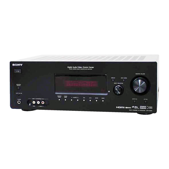
Sony STR-KG800 Service Manual
Multi channel
Hide thumbs
Also See for STR-KG800:
- Operating instructions manual (80 pages) ,
- Service manual (80 pages)
Table of Contents
Advertisement
QQ
3 7 63 1515 0
SERVICE MANUAL
Ver. 1.0 2008.02
• STR-KG800 is the receiver section in
HT-DDWG800.
This receiver incorporates Dolby* Digital and Pro Logic Surround and the DTS** Digital Surround
System.
* Manufactured under license from Dolby Laboratories. Dolby, Pro Logic, and the double-D sym-
bol are trademarks of Dolby Laboratories.
** Manufactured under license under U.S. Patent #'s: 5,451,942; 5,956,674; 5,974,380; 5,978,762;
6,487,535 & other U.S. and worldwide patents issued & pending. DTS and DTS Digital Sur-
round are registered trademarks and the DTS logos and Symbol are trademarks of DTS, Inc.
© 1996-2007 DTS, Inc. All Rights Reserved.
This receiver incorporates High-Defi nition Multimedia Interface (HDMITM) technology.
HDMI, the HDMI logo and High-Defi nition Multimedia Interface are trademarks or registered
TE
L 13942296513
trademarks of HDMI Licensing LLC.
"x.v.Colour" and "x.v.Colour" logo are trademarks of Sony Corporation.
"BRAVIA" and
are trademarks of Sony Corporation.
Amplifi er section
Power Output
1)
Models of area code CEL, CEK
Stereo mode (rated) (6 ohms, 1 kHz, THD 1%)
90 W + 90 W
Surround mode (reference) (6 ohms, 1 kHz, THD
10%)
RMS output
FRONT:135 W
per channel
CENTER:135 W
SURROUND:135 W
per channel
1)
Measured under the following conditions:
Area code
Power requirements
CEL, CEK
230 V AC, 50 Hz
2)
Reference power output for front, center and
surround speakers. Depending on the sound
fi eld settings and the source, there may be no
sound output.
www
.
Sony Corporation
9-887-956-01
2008B05-1
Audio Business Group
©
2008.02
Published by Sony Techno Create Corporation
http://www.xiaoyu163.com
Inputs
Analog
Digital (Coaxial) Impedance: 75 ohms
Outputs (Analog)
AUDIO OUT
2)
SUB WOOFER Voltage: 2 V/1 kohm
Reproduction frequency range:
Tone
Gain levels ±6 dB, 1 dB step
FM tuner section
Tuning range
Antenna
Antenna terminals 75 ohms, unbalanced
Intermediate frequency
x
ao
u163
y
i
http://www.xiaoyu163.com
STR-KG800
2 9
8
Q Q
3
6 7
1 3
1 5
SPECIFICATIONS
Sensitivity: 800 mV/
50 kohms
Voltage: 800 mV/
10 kohms
28 – 20,000 Hz
87.5 - 108.0 MHz
FM wire antenna
10.7 MHz
MULTI CHANNEL AV RECEIVER
co
.
9 4
2 8
AEP Model
UK Model
0 5
8
2 9
9 4
2 8
AM tuner section
Tuning range
Models of area code CEL, CEK
With 9-kHz tuning scale:
531 – 1,602 kHz
Antenna
Loop antenna
Intermediate frequency
450 kHz
Video section
Inputs/Outputs
Video:
1 Vp-p, 75 ohms
COMPONENT VIDEO:
Y: 1 Vp-p, 75 ohms
PB/CB: 0.7 Vp-p, 75 ohms
PR/CR: 0.7 Vp-p, 75 ohms
80 MHz HD Pass Through
– Continued on next page –
m
9 9
9 9
Advertisement
Table of Contents

Related Manuals for Sony STR-KG800


Summary of Contents for Sony STR-KG800
-
Page 1: Service Manual
This receiver incorporates High-Defi nition Multimedia Interface (HDMITM) technology. HDMI, the HDMI logo and High-Defi nition Multimedia Interface are trademarks or registered L 13942296513 trademarks of HDMI Licensing LLC. “x.v.Colour” and “x.v.Colour” logo are trademarks of Sony Corporation. “BRAVIA” and are trademarks of Sony Corporation. SPECIFICATIONS Amplifi... -
Page 2: Table Of Contents
COMPONENTS IDENTIFIED BY MARK 0 OR DOTTED LINE WITH MARK 0 ON THE SCHEMATIC DIAGRAMS AND IN THE PARTS LIST ARE CRITICAL TO SAFE OPERATION. REPLACE THESE COMPONENTS WITH SONY PARTS WHOSE PART NUMBERS APPEAR AS SHOWN IN THIS MANUAL OR IN SUPPLEMENTS PUBLISHED BY SONY. http://www.xiaoyu163.com... -
Page 3: Servicing Notes
STR-KG800 SECTION 1 SERVICING NOTES 3 7 63 1515 0 UNLEADED SOLDER Boards requiring use of unleaded solder are printed with the lead- free mark (LF) indicating the solder contains no lead. (Caution: Some printed circuit boards may not come printed with... -
Page 4: General
STR-KG800 SECTION 2 GENERAL This section is extracted 3 7 63 1515 0 from instruction manual. Receiver Front panel MASTER VOLUME DISPLAY INPUT MODE INPUT SELECTOR SPEAKERS (ON/OFF) AUTO CAL MIC MEMORY/ TUNING ENTER MODE TUNING A.F.D. MOVIE MUSIC... - Page 5 STR-KG800 3 7 63 1515 0 About the indicators on the display PLII MEMORY RDS ST HDMI COAX D.RANGE MONO Name Function Name Function Lights up when the audio signal Tuner Lights up when using the is output from the SUB...
- Page 6 STR-KG800 3 7 63 1515 0 Rear panel SAT IN DVD IN BD IN ANTENNA OPTICAL HDMI SAT IN DVD IN VIDEO 1 IN MONITOR OUT OPTICAL VIDEO VIDEO VIDEO VIDEO VIDEO FRONT COAXIAL MONITOR COMPONENT VIDEO DIGITAL (ASSIGNABLE)
- Page 7 DVD or Blu-ray disc on Remote Commander to operate the receiver on or off. the TV screen. Then, use , , and to control the Sony audio/video ) to perform AV / Press to turn on or off the menu operations.
- Page 8 STR-KG800 3 7 63 1515 0 Name Function Name Function Name Function MENU/HOME Press to display the menu of Press TV and the button with Numeric Press to buttons the VCR, DVD player, orange printing at the same – preset/tune to preset...
-
Page 9: Disassembly
STR-KG800 SECTION 3 DISASSEMBLY 3 7 63 1515 0 • This set can be disassembled in the order shown below. 3-1. DISASSEMBLY FLOW 3-2. CASE (Page 9) 3-3. BACK PANEL BLOCK (Page 10) 3-4. FRONT PANEL BLOCK 3-5. MAIN BLOCK... -
Page 10: Back Panel Block
STR-KG800 3 7 63 1515 0 3-3. BACK PANEL BLOCK back panel block connector (CNP911) connector clamp (CNP912) two connectors connector (CNP203, CNP204) (CN3509) nine screws (BVTP3 × 8) screw (BVTP3 × 8) five screws (BVTP3 × 8) two connectors... -
Page 11: Main Block
STR-KG800 3 7 63 1515 0 3-5. MAIN BLOCK three screws (BV3) two screws (BV3) connector (CN790) two connectors (CNP921, CNP940) main block three connectors (CNP430, CNP500, CNP930) L 13942296513 3-6. MAIN BOARD ten screws (transistor) screw five transistor MN2488-OPY-MK... -
Page 12: Test Mode
STR-KG800 SECTION 4 TEST MODE 3 7 63 1515 0 FL CHECK MODE SWAP ALL MODE All fl uorescent segments are tested. When this test is activated, all When this mode is used, output the audio signal of front L/R chan- segments turn on at the same time, then each segment turns on one nel to all channel. - Page 13 STR-KG800 3 7 63 1515 0 1. DCAC DSP Data Line Checking After press the [TUNING MODE] button, DCAC Factory test mode will start, below display will show: “DCAC x” x = 1, 2, 3, 4 If there is error happen, below display will show: “ERR SD0x”...
-
Page 14: Electrical Check
STR-KG800 SECTION 5 ELECTRICAL CHECK 3 7 63 1515 0 FM AUTO STOP CHECK signal generator Procedure: 1. Turn on the set. 2. Input the following signal from signal generator to FM antenna input directly. Carrier frequency: A = 87.5 MHz, B = 98 MHz, C = 108 MHz... -
Page 15: Diagrams
STR-KG800 SECTION 6 DIAGRAMS 3 7 6 3 1 5 1 5 0 6-1. BLOCK DIAGRAM - MAIN Section - DIGITAL AUDIO DATA SELECTOR INTERFACE RECEIVER IC1302 IC1301 DATA0, BCK SPDIF LRCK, CKOUT (Page 16) (Page 17) DATAO 16... -
Page 16: Block Diagram - Hdmi Section
STR-KG800 3 7 6 3 1 5 1 5 0 6-2. BLOCK DIAGRAM - HDMI Section - (Page 15) DATA0+ DATA0– DATA1+ DATA1– TX0+ 30 DATA0+ TX0– 29 DATA0– DATA2+ DATA2– Y2 31 RX0+ TX1+ 33 DATA1+ CN3501 Z2 32 RX0–... -
Page 17: Block Diagram - Dsp Section
STR-KG800 3 7 6 3 1 5 1 5 0 6-3. BLOCK DIAGRAM - DSP Section - IC1009 DATA0, BCK, LRCK, CKOUT DATA0 (Page 15) 78 DPSIA INPUT SELECTOR IC1008 D_AUDIO D/A CONVERTER (Page 15) 2 A0 IC1452 SD0-3, MCK, BCK, LRCK... -
Page 18: Block Diagram - Audio Section
STR-KG800 3 7 6 3 1 5 1 5 0 6-4. BLOCK DIAGRAM - AUDIO Section - INPUT SELECTOR, ELECTRICAL VOLUME IC400 A_AUDIO (Page 15) INL9 LOUT 76 TV IN J401 (2/2) RECL1 29 R-CH SA-CD/CD J401 (1/2) CD-R OUT... -
Page 19: Block Diagram - Power Supply Section
STR-KG800 3 7 6 3 1 5 1 5 0 6-5. BLOCK DIAGRAM - POWER SUPPLY Section - FLUORESCENT INDICATOR TUBE DRIVER SYSTEM CONTROLLER IC100 IC1010 (4/4) 71 FL_DATA LEVEL SHIFT 70 FL_CLK REGULATOR DMPORT +5V IC101 69 FL LAT... - Page 20 STR-KG800 3 7 6 3 1 5 1 5 0 THIS NOTE IS COMMON FOR PRINTED WIRING BOARDS AND SCHEMATIC DIAGRAMS. • Circuit Boards Location (In addition to this, the necessary note is printed in each block.) STANDBY board For Printed Wiring Boards.
-
Page 21: Printed Wiring Board - Main Board
STR-KG800 3 7 6 3 1 5 1 5 0 6-6. PRINTED WIRING BOARD - MAIN Board - • See page 20 for Circuit Boards Location. • : Uses unleaded solder. J401 J403 J404 SPEAKERS SA-CD/CD/ SA-CD/CD/ TB604 TB601... -
Page 22: Schematic Diagram - Main Board (1/3)
STR-KG800 3 7 6 3 1 5 1 5 0 6-7. SCHEMATIC DIAGRAM - MAIN Board (1/3) - • See page 46 for IC Block Diagrams. MAIN BOARD (1/3) MAIN BOARD (3/3) (Page MAIN BOARD (2/3) (Page R830 C771... -
Page 23: Schematic Diagram - Main Board (2/3)
STR-KG800 3 7 6 3 1 5 1 5 0 6-8. SCHEMATIC DIAGRAM - MAIN Board (2/3) - • See page 46 for IC Block Diagrams. MAIN (Page 22) BOARD (1/3) MAIN BOARD (2/3) MAIN MAIN BOARD BOARD (1/3) -
Page 24: Schematic Diagram - Main Board (3/3)
STR-KG800 3 7 6 3 1 5 1 5 0 6-9. SCHEMATIC DIAGRAM - MAIN Board (3/3) - CN792 MAIN BOARD (3/3) HP_DETECT R940 CNP940 R392 RY375 0.15 1/2W R-CH R4 +AC R393 HEADPHONE R4 -AC BOARD CNP790 L-CH... -
Page 25: Schematic Diagram - Digital Ab Board (1/5)
STR-KG800 3 7 6 3 1 5 1 5 0 6-10. SCHEMATIC DIAGRAM - DIGITAL AB Board (1/5) - • See page 33 for Waveforms. • See page 46 for IC Block Diagrams. DIGITAL AB BOARD (1/5) CNS512 DIGITAL C1011 0.01... -
Page 26: Schematic Diagram - Digital Ab Board (2/5)
STR-KG800 3 7 6 3 1 5 1 5 0 6-11. SCHEMATIC DIAGRAM - DIGITAL AB Board (2/5) - • See page 46 for IC Block Diagrams. DIGITAL AB BOARD (2/5) R1200 DIGITAL AB BOARD (3/5) (Page 27) FB1453... -
Page 27: Q Q 6-12. Schematic Diagram - Digital Ab Board (3/5)
STR-KG800 3 7 6 3 1 5 1 5 0 6-12. SCHEMATIC DIAGRAM - DIGITAL AB Board (3/5) - • See page 33 for Waveforms. • See page 46 for IC Block Diagrams. • See page 53 for IC Pin Function Description. -
Page 28: Schematic Diagram - Digital Ab Board (4/5)
STR-KG800 3 7 6 3 1 5 1 5 0 6-13. SCHEMATIC DIAGRAM - DIGITAL AB Board (4/5) - • See page 46 for IC Block Diagrams. (Page 45) MAIN (Page 24) BOARD DCDC MAIN STANDBY (3/3) (Page 43) -
Page 29: Schematic Diagram - Digital Ab Board (5/5)
STR-KG800 3 7 6 3 1 5 1 5 0 6-14. SCHEMATIC DIAGRAM - DIGITAL AB Board (5/5) - • See page 33 for Waveforms. • See page 53 for IC Pin Function Description. DIGITAL (Page 28) AB BOARD... -
Page 30: Printed Wiring Board - Digital Ab Board (Component Side)
STR-KG800 3 7 6 3 1 5 1 5 0 6-15. PRINTED WIRING BOARD - DIGITAL AB Board (Component Side) - • See page 20 for Circuit Boards Location. • : Uses unleaded solder. • Semiconductor Location Ref. No. Location... -
Page 31: Printed Wiring Board - Digital Ab Board (Conductor Side)
STR-KG800 3 7 6 3 1 5 1 5 0 6-16. PRINTED WIRING BOARD - DIGITAL AB Board (Conductor Side) - • See page 20 for Circuit Boards Location. • : Uses unleaded solder. • Semiconductor Location Ref. No. Location... -
Page 32: Printed Wiring Boards - Mic/Headphone Section
STR-KG800 3 7 6 3 1 5 1 5 0 6-17. PRINTED WIRING BOARDS - MIC/HEADPHONE Section - • See page 20 for Circuit Boards Location. • : Uses unleaded solder. (Page 21) MAIN BOARD CN792 DCAC BOARD HEADPHONE BOARD... -
Page 33: Schematic Diagram - Mic/Headphone Section
STR-KG800 3 7 6 3 1 5 1 5 0 6-18. SCHEMATIC DIAGRAM - MIC/HEADPHONE Section - • Waveforms – DIGITAL AB Board – – HDMI Board – – DISPLAY Board – IC1301 (XOUT) IC3511 (XTALOUT) IC100 (OSC) DCAC BOARD... -
Page 34: Printed Wiring Board - Hdmi Board (Side A)
STR-KG800 3 7 6 3 1 5 1 5 0 6-19. PRINTED WIRING BOARD - HDMI Board (Side A) - • See page 20 for Circuit Boards Location. • : Uses unleaded solder. HDMI BOARD HDMI (SIDE A) BD IN... -
Page 35: Printed Wiring Board - Hdmi Board (Side B)
STR-KG800 3 7 6 3 1 5 1 5 0 6-20. PRINTED WIRING BOARD - HDMI Board (Side B) - • See page 20 for Circuit Boards Location. • : Uses unleaded solder. HDMI BOARD (SIDE B) R3502 R3504... -
Page 36: Schematic Diagram - Hdmi Board (1/2)
STR-KG800 3 7 6 3 1 5 1 5 0 6-21. SCHEMATIC DIAGRAM - HDMI Board (1/2) - • See page 33 for Waveforms. • See page 46 for IC Block Diagrams. • See page 53 for IC Pin Function Description. -
Page 37: Schematic Diagram - Hdmi Board (2/2)
STR-KG800 3 7 6 3 1 5 1 5 0 6-22. SCHEMATIC DIAGRAM - HDMI Board (2/2) - • See page 33 for Waveforms. • See page 46 for IC Block Diagrams. • See page 53 for IC Pin Function Description. -
Page 38: Printed Wiring Boards - Video Section
STR-KG800 3 7 6 3 1 5 1 5 0 6-23. PRINTED WIRING BOARDS - VIDEO Section - • See page 20 for Circuit Boards Location. • : Uses unleaded solder. • Semiconductor Location Ref. No. Location D210 J221... -
Page 39: Schematic Diagram - Video Section
STR-KG800 3 7 6 3 1 5 1 5 0 6-24. SCHEMATIC DIAGRAM - VIDEO Section - • See page 46 for IC Block Diagrams. COMPONENT VIDEO SAT IN MONITOR VIDEO 1 VIDEO OUT VIDEO IN VIDEO OUT VIDEO IN... -
Page 40: Printed Wiring Boards - Panel Section
STR-KG800 3 7 6 3 1 5 1 5 0 6-25. PRINTED WIRING BOARDS - PANEL Section - • See page 20 for Circuit Boards Location. • : Uses unleaded solder. DISPLAY BOARD CN108 R197 JW241 JW233 MAIN BOARD... -
Page 41: Schematic Diagram - Panel Section
STR-KG800 3 7 6 3 1 5 1 5 0 6-26. SCHEMATIC DIAGRAM - PANEL Section - • See page 33 for Waveforms. • See page 46 for IC Block Diagrams. DISPLAY BOARD FL101 FLUORESCENT INDICATOR TUBE POWER BOARD... -
Page 42: Printed Wiring Board - Dcdc Converter Board
STR-KG800 3 7 6 3 1 5 1 5 0 6-27. PRINTED WIRING BOARD - DCDC CONVERTER Board - • See page 20 for Circuit Boards Location. • : Uses unleaded solder. DCDC CONVERTER BOARD FH4002 FH4004 D4001 JW4001... -
Page 43: Dcdc Converter Board
STR-KG800 3 7 6 3 1 5 1 5 0 6-28. SCHEMATIC DIAGRAM - DCDC CONVERTER Board - • See page 46 for IC Block Diagrams. DCDC CONVERTER BOARD IC4001 SI-8050S-LF1101 IC B/D IC4001 +5V REGULATOR CN4101 +6.3V L4001... -
Page 44: Printed Wiring Board - Standby Board
STR-KG800 3 7 6 3 1 5 1 5 0 6-29. PRINTED WIRING BOARD - STANDBY Board - • See page 20 for Circuit Boards Location. • : Uses unleaded solder. • Semiconductor Location Ref. No. Location D901 STANDBY BOARD... -
Page 45: Schematic Diagram - Standby Board
STR-KG800 3 7 6 3 1 5 1 5 0 6-30. SCHEMATIC DIAGRAM - STANDBY Board - STANDBY BOARD R910 CNP911 0.22 1/2W AC-R2-17V AC-R2-17V CN912 R911 0.22 DCDC +15V 1/2W CONVERTER C910 BOARD AC-R2-17V CN4001 R2 GND IN... - Page 46 STR-KG800 3 7 6 3 1 5 1 5 0 • IC Block Diagrams – MAIN Board – IC400 BD3471KS2 IC600, 700, 800 μPC2581V-S BIAS CIRCUIT PROTECTOR SUB1 SWITCH SWITCH SWITCH SWITCH HPFN DRIVE DRIVE LPF01 DRIVE DRIVE LPF02...
- Page 47 STR-KG800 3 7 63 1515 0 IC1302 TC74ACT153F (EL) DATA INPUTS STROBE OUTPUT 2C2 2C1 2C0 SELECT 2C3 2C2 2C1 2C0 1C3 1C2 1C1 1C0 STROBE 1C3 1C2 1C1 1C0 OUTPUT SELECT DATA INPUTS IC1401 PCM1808PWR ANTIALIAS VINR LOW-PASS FILTER...
- Page 48 STR-KG800 3 7 63 1515 0 – HDMI Board – IC3503 TMDS341APFCR 80 79 RX W/EQ RX W/EQ RX W/EQ RX W/EQ SDA1 RX W/EQ SCL1 RX W/EQ RX W/EQ RX W/EQ RX W/EQ RX W/EQ RX W/EQ RX W/EQ...
- Page 49 STR-KG800 3 7 63 1515 0 IC3509 BR24L02F-WE2 2kbit EEPROM ARRAY 8bit ADDRESS SLAVE/ WORD DATA DECODER ADDRESS REGISTER REGISTER 8 VCC 7 WP 6 SCL CONTROL LOGIC HIGH VOLTAGE VCC LEVEL GENERATOR DETECT IC3513 SII9030CTU-7 HSYNC 60 CGND...
- Page 50 STR-KG800 3 7 63 1515 0 IC3516 TK11150CSCL-G IC3526, 3527 SI-3033KM-TL OVER HEAT & OVER CURRENT PROTECTION CONTROL – CIRCUIT – BANDGAP REFERENCE VOUT – VIDEO Board – IC210 NJM2595M-TE2 VOUT1 DRIVER L 13942296513 VIN5 16 V+ VIN4 DRIVER...
- Page 51 STR-KG800 3 7 63 1515 0 IC220 NJM2586AM DRIVER CONT1 CH1 IN1 24 CH1 OUT BIAS CONT2 CH1 IN2 23 PS DRIVER CONT1 BIAS 22 CH2 OUT CH1 IN3 BIAS 21 V+2 DRIVER CONT1 CH2 IN1 20 CH3 OUT...
- Page 52 STR-KG800 3 7 63 1515 0 – DCDC CONVERTER Board – IC4001 SI-8050S-LF1101 IC4100 SI-8033S OVER REGULATOR CURRENT PROTECTOR LATCH RESET & DRIVER OVER HEAT – PROTECTOR COMPARATOR – VREF ERROR AMP L 13942296513 u163 http://www.xiaoyu163.com...
- Page 53 STR-KG800 3 7 63 1515 0 • IC Pin Function Description DIGITAL BOARD IC1009 ADSST-AVR-1115 (DSP) Pin No. Pin Name Description VDDINT Power supply terminal (+1.2V) 2, 3 CLKCFG0, CLKCFG1 Clock frequency setting terminal BOOTCFG0, 4, 5 Boot mode setting terminal for DSP...
- Page 54 STR-KG800 3 7 63 1515 0 Pin No. Pin Name Description DPSOD PCM audio signal (surround back L/R) output to the D/A converter VDDINT Power supply terminal (+1.2V) VDDEXT Power supply terminal (+3.3V) Ground terminal VDDINT Power supply terminal (+1.2V)
- Page 55 STR-KG800 3 7 63 1515 0 Pin No. Pin Name Description Ground terminal CLKOUT Not used XEMU Not used Not used Not used CTRST Not used Not used Not used Ground terminal CLKIN System clock input terminal (25 MHz)
- Page 56 STR-KG800 3 7 63 1515 0 DIGITAL BOARD IC1010 MB91353APMT-G-117E1 (SYSTEM CONTROLLER) Pin No. Pin Name Description DAC CLK Clock signal output to the D/A converter XMDACMS Serial data latch pulse signal output terminal Not used XMDACMD1 Serial data output terminal...
- Page 57 STR-KG800 3 7 63 1515 0 Pin No. Pin Name Description DSP_RESET System reset signal output to the DSP DSP_SPIDS(LAT) Serial data latch pulse signal output to the DSP 74ACT153_B Data selection signal output terminal 74ACT154_A Data selection signal output terminal...
- Page 58 STR-KG800 3 7 63 1515 0 HDMI BOARD IC3511 SII9011CLU (HDMI RECEIVER) Pin No. Pin Name Description VSYNC Vertical synchronize signal output for the HDMI transceiver 2 to 5 QO23 to QO20 Not used IOGND Ground terminal IOVCC Power supply terminal (+3.3V)
- Page 59 STR-KG800 3 7 63 1515 0 Pin No. Pin Name Description IOGND Ground terminal MCLK Audio master clock signal output for the DSP and HDMI transceiver CGND Ground terminal CVCC18 Power supply terminal (+1.8V) AUDPVCC18 Power supply terminal (+1.8V)
- Page 60 STR-KG800 3 7 63 1515 0 HDMI RE BOARD IC3519 M30620FCPGP-RSX01 (HDMI CONTROLLER) Pin No. Pin Name Description 1 to 5 Not used BYTE Not used CNVSS Processor mode switch input terminal (for test) 8, 9 Not used RESET System reset signal input from the main system controller "L": reset...
-
Page 61: Exploded Views
STR-KG800 SECTION 7 EXPLODED VIEWS 3 7 63 1515 0 Note: • -XX and -X mean standardized parts, so • The mechanical parts with no reference The components identifi ed by mark 0 they may have some difference from the... -
Page 62: Back Panel Section
STR-KG800 3 7 63 1515 0 7-2. BACK PANEL SECTION not supplied not supplied (STANDBY board) (UK) F901 not supplied L 13942296513 not supplied Note: If wire (fl at type) is replaced, install it after bending it in the same form as that before replacement. -
Page 63: Main Section
STR-KG800 3 7 63 1515 0 7-3. MAIN SECTION supplied with Q653, Q654, Q703, Q704, Q753, Q754, Q803, Q804, Q853, Q854 Q803 Q853 Q804 Q703 Q753 Q854 not supplied Q704 not supplied Q754 Q653 (WIRE ROUTE board) Q654 not supplied... -
Page 64: Electrical Parts List
STR-KG800 SECTION 8 DCAC DCDC CONVERTER ELECTRICAL PARTS LIST 3 7 63 1515 0 Note: • Due to standardization, replacements in • RESISTORS When indicating parts by reference num- the parts list may be different from the All resistors are in ohms. - Page 65 STR-KG800 DCDC CONVERTER DIGITAL AB 3 7 63 1515 0 Ref. No. Part No. Description Remark Ref. No. Part No. Description Remark L4102 1-456-721-11 COIL, CHOKE 100uH C1070 1-125-777-11 CERAMIC CHIP 0.1uF < RESISTOR > C1072 1-125-777-11 CERAMIC CHIP 0.1uF...
- Page 66 STR-KG800 DIGITAL AB 3 7 63 1515 0 Ref. No. Part No. Description Remark Ref. No. Part No. Description Remark C1171 1-162-970-11 CERAMIC CHIP 0.01uF C1462 1-115-412-11 CERAMIC CHIP 680PF C1172 1-162-970-11 CERAMIC CHIP 0.01uF C1463 1-164-934-11 CERAMIC CHIP 330PF...
- Page 67 IC TC7WU04FU (TE12R) < DIODE > IC1351 6-600-466-01 IC TORX147L (SONY) (DIGITAL OPTICAL SAT IN) D1001 8-719-053-18 DIODE 1SR154-400TE-25 IC1352 6-600-466-01 IC TORX147L (SONY) (TV OPTICAL IN) D1003 8-719-049-09 DIODE 1SS367-T3SONY D1004 8-719-049-09 DIODE 1SS367-T3SONY IC1401 6-710-554-01 IC PCM1808PWR D1106...
- Page 68 STR-KG800 DIGITAL AB 3 7 63 1515 0 Ref. No. Part No. Description Remark Ref. No. Part No. Description Remark R1047 1-216-801-11 METAL CHIP 1/10W R1137 1-216-809-11 METAL CHIP 1/10W R1048 1-216-857-11 METAL CHIP 1/10W R1138 1-216-809-11 METAL CHIP...
- Page 69 STR-KG800 DIGITAL AB DISPLAY 3 7 63 1515 0 Ref. No. Part No. Description Remark Ref. No. Part No. Description Remark R1325 1-216-820-11 METAL CHIP 1/10W R1644 1-216-833-11 METAL CHIP 1/10W R1326 1-216-809-11 METAL CHIP 1/10W R1645 1-216-833-11 METAL CHIP...
- Page 70 STR-KG800 DISPLAY HDMI 3 7 63 1515 0 Ref. No. Part No. Description Remark Ref. No. Part No. Description Remark R118 1-216-844-11 METAL CHIP 1/10W C3531 1-107-826-11 CERAMIC CHIP 0.1uF R119 1-216-809-11 METAL CHIP 1/10W C3533 1-107-826-11 CERAMIC CHIP 0.1uF...
- Page 71 STR-KG800 HDMI 3 7 63 1515 0 Ref. No. Part No. Description Remark Ref. No. Part No. Description Remark C3630 1-107-826-11 CERAMIC CHIP 0.1uF Q3505 6-551-696-01 TRANSISTOR ISA1235AC1TP-1EF C3631 1-107-826-11 CERAMIC CHIP 0.1uF Q3506 6-551-696-01 TRANSISTOR ISA1235AC1TP-1EF C3632 1-107-826-11 CERAMIC CHIP 0.1uF...
- Page 72 STR-KG800 HDMI HEADPHONE MAIN 3 7 63 1515 0 Ref. No. Part No. Description Remark Ref. No. Part No. Description Remark R3589 1-216-864-11 SHORT CHIP R3779 1-216-805-11 METAL CHIP 1/10W R3590 1-216-864-11 SHORT CHIP R3780 1-216-805-11 METAL CHIP 1/10W...
- Page 73 STR-KG800 MAIN 3 7 63 1515 0 Ref. No. Part No. Description Remark Ref. No. Part No. Description Remark C431 1-162-960-11 CERAMIC CHIP 220PF C804 1-162-927-11 CERAMIC CHIP 100PF C449 1-162-927-11 CERAMIC CHIP 100PF C805 1-107-583-11 CERAMIC 0.25PF 500V...
- Page 74 STR-KG800 MAIN 3 7 63 1515 0 Ref. No. Part No. Description Remark Ref. No. Part No. Description Remark CC55 1-162-927-11 CERAMIC CHIP 100PF IC800 6-700-943-01 IC uPC2581V-S CC58 1-162-927-11 CERAMIC CHIP 100PF IC3002 8-759-710-97 IC NJM4565M-D CC59 1-162-927-11 CERAMIC CHIP 100PF <...
- Page 75 STR-KG800 MAIN 3 7 63 1515 0 Ref. No. Part No. Description Remark Ref. No. Part No. Description Remark Q851 8-729-119-76 TRANSISTOR 2SA1175-HFE 0 R488 1-249-385-91 CARBON 1/4W Q852 8-729-141-30 TRANSISTOR 2SC3623A-LK R501 1-216-837-11 METAL CHIP 1/10W Q861 8-729-216-31...
- Page 76 STR-KG800 MAIN POWER 3 7 63 1515 0 Ref. No. Part No. Description Remark Ref. No. Part No. Description Remark R723 1-216-837-11 METAL CHIP 1/10W R856 1-216-825-11 METAL CHIP 2.2K 1/10W R724 1-216-837-11 METAL CHIP 1/10W R857 1-216-844-11 METAL CHIP...
- Page 77 STR-KG800 POWER STANDBY VIDEO 3 7 63 1515 0 Ref. No. Part No. Description Remark Ref. No. Part No. Description Remark < SWITCH > 0 R911 1-243-634-11 FUSIBLE 0.22 1/2W S100 1-771-410-21 SWITCH, TACTILE (I/1) R955 1-216-825-11 METAL CHIP 2.2K...
- Page 78 STR-KG800 VIDEO VIDEO2 3 7 63 1515 0 Ref. No. Part No. Description Remark Ref. No. Part No. Description Remark < JACK > 0 F4001 1-532-465-33 FUSE (T3.15AL/250V) 0 F4002 1-532-465-33 FUSE (T3.15AL/250V) J210 1-815-043-11 JACK, PIN 2P (MONITOR VIDEO OUT,...
- Page 79 STR-KG800 3 7 63 1515 0 MEMO L 13942296513 u163 http://www.xiaoyu163.com...
- Page 80 STR-KG800 3 7 63 1515 0 REVISION HISTORY Checking the version allows you to jump to the revised page. Also, clicking the version at the top of the revised page allows you to jump to the next revised page.
Need help?
Do you have a question about the STR-KG800 and is the answer not in the manual?
Questions and answers