Table of Contents
Advertisement
SERVICE MANUAL
Ver. 1.1 2006.05
• STR-K880 is the tuner and the amplifier section
in HT-DDW880, STR-K900 is the tuner and the
amplifier section in HT-DDW900.
Manufactured under license from Dolby Laboratories.
"Dolby", "Pro Logic" and the double-D symbol are trademarks of
Dolby Laboratories.
"DTS" and "DTS Digital Surround" are registered trademarks of
Digital Theater Systems, Inc.
POWER OUTPUT AND TOTAL
HARMONIC DISTORTION:
(Models of area code US only)
With 6 ohm loads, both channels driven, from
120 – 20,000 Hz; rated 90 watts per channel
minimum RMS power, with no more than
0.7% total harmonic distortion from 250
milliwatts to rated output.
Amplifier section
1)
Power Output
Models of area code US, CND
(6 ohms 1 kHz, THD 0.7%)
2)
FRONT
:
90 W/ch
2)
CENTER
:
90 W
2)
SUR
:
90 W/ch
(6 ohms 1 kHz, THD 10%)
2)
FRONT
:
140 W/ch
2)
CENTER
:
140 W
2)
SUR
:
140 W/ch
Models of area code AEP, UK, SP, SP6, E51
(6 ohms 1 kHz, THD 0.7%)
2)
FRONT
:
90 W/ch
2)
CENTER
:
90 W
2)
SUR
:
90 W/ch
2)
SUR BACK
:
90 W
Sony Corporation
9-887-101-02
Home Audio Division
2006E16-1
Published by Sony Techno Create Corporation
© 2006.05
STR-K880/K900
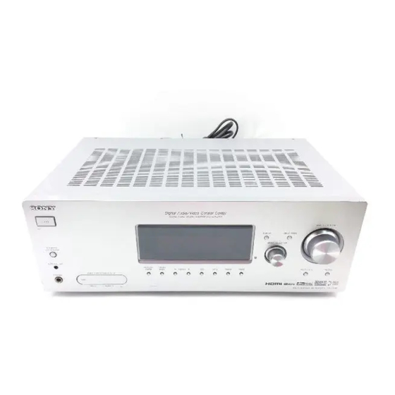
Photo : STR-K880
SPECIFICATIONS
(6 ohms 1 kHz, THD 10%)
2)
FRONT
:
135 W/ch
2)
CENTER
:
135 W
2)
SUR
:
135 W/ch
2)
SUR BACK
:
135 W
Models of area code AUS
(6 ohms 120 Hz – 20 kHz, THD 0.09%)
2)
FRONT
:
70 W/ch
2)
CENTER
:
70 W
2)
SUR
:
70 W/ch
2)
SUR BACK
:
70 W
(6 ohms 1 kHz, THD 0.7%)
2)
FRONT
:
90 W/ch
2)
CENTER
:
90 W
2)
SUR
:
90 W/ch
2)
SUR BACK
:
90 W
(6 ohms 1 kHz, THD 10%)
2)
FRONT
:
135 W/ch
2)
CENTER
:
135 W
2)
SUR
:
135 W/ch
2)
SUR BACK
:
135 W
Canadian Model
Australian Model
1)
Measured under the following conditions:
Area code
US, CND
AEP,UK,SP,SP6
E51, AUS
2)
Depending on the sound field settings and the
source, there may be no sound output.
Inputs (Analog)
MULTI CH IN,
SA-CD/CD,
MD/TAPE, DVD,
VIDEO 1, 2, 3
Inputs (Digital)
DVD (Coaxial)
VIDEO 1, 2
(Optical)
Outputs (Analog)
MD/TAPE (OUT),
VIDEO 1 (AUDIO
OUT)
SUB WOOFER
MULTI CHANNEL AV RECEIVER
US Model
STR-K900
AEP Model
UK Model
E Model
STR-K880
Power requirements
120 V AC, 60 Hz
230 V AC, 50 Hz
240 V AC, 50 Hz
Sensitivity: 800 mV
Impedance: 50 kohms
Sensitivity: –
Impedance: 75 ohms
Sensitivity: –
Impedance: –
Voltage: 800 mV
Impedance: 10 kohms
Voltage: 2 V
Impedance: 1 kohm
— Continued on next page —
Advertisement
Table of Contents

Related Manuals for Sony STR-K900 - Fm Stereo/fm-am Receiver


Summary of Contents for Sony STR-K900 - Fm Stereo/fm-am Receiver
-
Page 1: Service Manual
HT-DDW880, STR-K900 is the tuner and the amplifier section in HT-DDW900. Manufactured under license from Dolby Laboratories. “Dolby”, “Pro Logic” and the double-D symbol are trademarks of Dolby Laboratories. “DTS” and “DTS Digital Surround” are registered trademarks of Digital Theater Systems, Inc. - Page 2 AEP, UK models 2-663-098-2[] E51 model 2-663-098-3[] than ordinary solder. Ordinary soldering irons can be used but the iron tip has to be SP, SP6 models 2-663-098-4[] applied to the solder joint for a slightly longer time. AUS model 2-663-098-5[] Soldering irons using a temperature regulator should be set to •...
-
Page 3: Table Of Contents
LEAKAGE TEST 3-1. Block Diagram – MAIN Section – ........16 The AC leakage from any exposed metal part to earth ground and 3-2. Block Diagram – DISPLAY/POWER Section – ..... 17 from all exposed metal parts to any exposed metal part having a 3-3. -
Page 4: Front Panel Features And Descriptions
To remove the cover Name Function Press PUSH. I MULTI CH IN Press to select the audio When you remove the cover, keep it out of directly from the reach from children. components connected to the MULTI CH IN jacks. Name... - Page 5 Game decoder is activated. “; PRO LOGIC IIx” lights up M COAX Lights up when INPUT MODE * Except for models of area code E51. when the Pro Logic IIx Movie/ is set to “AUTO” and the source Music/Game decoder is signal is a digital signal being activated.
- Page 6 When playing a DTS format B LFE Lights up when the disc being channel indicate the channels being disc, be sure that you have made played back contains an LFE indicators played back. The boxes around digital connections and that...
- Page 7 Red (R) player. jack sound. VIDEO IN/ Yellow OUT jack HDMI IN/ Connects to a DVD MONITOR player, or a satellite a)b) OUT jack tuner. The image and the sound are output to a TV or a projector.
-
Page 8: Speaker Section
Remote commander OUTPUT section You can use the supplied remote RM-AAP013 COMPONENT Connects to a DVD Green to operate the receiver and to control the Sony VIDEO player, TV, or a INPUT/ satellite tuner. You audio/video components that the remote is... - Page 9 VOL + /– of all speakers at the same time. press ?/1 and AV ?/1 (A) at L AMP MENU Press to display the menu of the the same time (SYSTEM STANDBY). receiver. Then, use the control buttons to perform menu...
- Page 10 Name Function Z TUNING +/– V AV MENU Press to scan a station. Press to display the menus of the VCR, DVD player, satellite ./> Press to skip tracks of the tuner, Blu-ray disc recorder, VCR, CD player, VCD player,...
- Page 11 Press to set up the remote. – preset/tune to preset stations. The MASTER VOL +, TV VOL +, TV CH + and – select track numbers of the H buttons have tactile dots. Use the tactile dots as CD player, VCD player, LD references when operating the receiver.
-
Page 12: Test Mode
AM CHANNEL STEP 9 kHz/10 kHz SOFTWARE VERSION DISPLAY MODE SELECTION MODE The software version is displayed. Either the 9 kHz step or 10 kHz step can be selected for the AM Procedure: channel step. 1. While depressing the SPEAKERS (OFF/A/B/A+B) and the... - Page 13 Afterward, press the TUNING MODE to start DCAC factory test mode. 1. DCAC DSP Data Line Checking After press the TUNING MODE , DCAC Factory test mode will start, below display will show: “DCAC[][][]x” x = 1, 2, 3, 4 If there is error happen, below display will show: “ERR[]SD0x”...
-
Page 14: Diagrams
STR-K880/K900 Ver. 1.1 SECTION 3 DIAGRAMS THIS NOTE IS COMMON FOR PRINTED WIRING BOARDS AND SCHEMATIC DIAGRAMS. (In addition to this, the necessary note is printed in each block.) For Schematic Diagrams. For Printed Wiring Boards. Note: Note: • X : parts extracted from the component side. - Page 15 • Circuit Boards Location • Waveforms – DIGITAL Board – IC1501 9 (MCLK1) 3.4 Vp-p STANDBY board 72 ns AC SELECT board (E51 only) 1 V/DIV, 40 ns/DIV SPEAKER board IC1101 id (X1) VIDEO board SPEAKER B board HDMI board POWER board 4.2 Vp-p...
-
Page 16: Block Diagram - Main Section
STR-K880/K900 3-1. BLOCK DIAGRAM – MAIN SECTION – IC401 ANALOG SOUND PROCESSOR J402 • R-CH is omitted due to same as L-CH. SA-CD/CD INGL • Signal Path J404 (2/2) J404 (1/2) ROUTAL AUDIO OUT VIDEO 1 : FM VIDEO 1... -
Page 17: Block Diagram - Display/Power Section
PHONES POWER AMP RY791 Q703 +V OUT2 Q790 BOOSTER RELAY DRIVE Q701,702 LIMITER TM601 • R-CH is omitted due to same as L-CH. • Signal Path FRONT A Q740 R-CH AF POWER RY701 PROTECT Q710 : FM Q705,706 RELAY Q704... -
Page 18: Printed Wiring Board - Digital Board (Side A)
STR-K880/K900 3-3. PRINTED WIRING BOARD – DIGITAL BOARD (SIDE A) – • See page 15 for Circuit Boards Location. :Uses unleaded solder. • Semiconductor Location EXCEPT AEP,UK Ref. No. Location D1001 AEP,UK D1301 D1302 D1501 D1502 IC1101 IC1111 IC1131 IC1301... -
Page 19: Printed Wiring Board - Digital Board (Side B)
STR-K880/K900 3-4. PRINTED WIRING BOARD – DIGITAL BOARD (SIDE B) – • See page 15 for Circuit Boards Location. :Uses unleaded solder. STANDBY MAIN VIDEO BOARD BOARD BOARD CNP903 CNP912 TUNER UNIT CNS203 (Page 31) (Page 25) (Page 37) • Semiconductor... -
Page 20: Schematic Diagram - Digital Board (1/5)
STR-K880/K900 3-5. SCHEMATIC DIAGRAM – DIGITAL BOARD (1/5) – • See page 15 for Waveform. • See page 41 for IC Block Diagram. CNS508 JR1202 R1261 C1251 R1260 C1252 C1253 R1252 R1251 IC1902 IC1071 TA7809LS TA78033LS C1914 C1064 C1063 C1913... -
Page 21: Schematic Diagram - Digital Board (2/5)
STR-K880/K900 3-6. SCHEMATIC DIAGRAM – DIGITAL BOARD (2/5) – • See page 15 for Waveform. • See page 42 for IC Block Diagram. C1520 IC1502 IS61WV6416BLL FB1502 -12TLI C1516 C1515 JR1016 C1518 C1517 FB1501 C1519 RB1501 RB1506 RB1504 R1501 RB1502... -
Page 22: Schematic Diagram - Digital Board (3/5)
STR-K880/K900 3-7. SCHEMATIC DIAGRAM – DIGITAL BOARD (3/5) – • See page 41, 43 for IC Block Diagrams. C1450 R1474 C1460 C1494 FB1453 C1457 C1454 10 50V IC1452 PCM1609APT R1402 C1491 10 50V 2.2k C1404 IC1401 PCM1800E12K R1401 FB1452 C1409 R1421 6.8k... -
Page 23: Schematic Diagram - Digital Board (4/5)
STR-K880/K900 Ver. 1.1 3-8. SCHEMATIC DIAGRAM – DIGITAL BOARD (4/5) – • See page 42 for IC Block Diagrams. CNP505 IC1031 IC1904 D1001 BA50BC0T BA033BCOT 1SR154-400TE-25 C1105 C1104 C1022 C1032 C1021 C1031 CNP503 D1108 1SS355TE-17 D1107 1SS355TE-17 D1110 1SS355TE-17 C1905... -
Page 24: Schematic Diagram - Digital Board (5/5)
STR-K880/K900 Ver. 1.1 3-9. SCHEMATIC DIAGRAM – DIGITAL BOARD (5/5) – • See page 15 for Waveform. • See page 46 for IC Pin Function Description. R1112 R1058 R1083 R1113 R1111 R1094 R1115 2.2k R1095 C1100 R1122 R1035 2.2k R1123... -
Page 25: Printed Wiring Board - Main Board
STR-K880/K900 Ver. 1.1 3-10. PRINTED WIRING BOARD – MAIN BOARD – • See page 15 for Circuit Boards Location. :Uses unleaded solder. VIDEO SPEAKER B SA-CD/CD MD/TAPE VIDEO 2 VIDEO 1 MULTI CH IN SPEAKER WOOFER BOARD BOARD BOARD VIDEO 3... -
Page 26: Schematic Diagram - Main Board (1/3)
STR-K880/K900 Ver. 1.1 3-11. SCHEMATIC DIAGRAM – MAIN BOARD (1/3) – WP100 SYSTEM GND J402 CNP501 CC52 R452 100P CC02 R402 100P C702 10 50V C464 C762 CC59 R459 C459 10 50V 100P C495 C490 C485 CC09 R409 C409 100P... -
Page 27: Schematic Diagram - Main Board (2/3)
STR-K880/K900 Ver. 1.1 3-12. SCHEMATIC DIAGRAM – MAIN BOARD (2/3) – • See page 43 for IC Block Diagrams. CN807 IC701 R719 C720 4.7k 220p Q740 C717 R714 2SC1815GR-TPE2 Q701 2SA1115TP-EF R744 R740 C742 D740 Q705 0.01 1SS133T-72 CN792 2SA1038S... -
Page 28: Schematic Diagram - Main Board (3/3)
STR-K880/K900 3-13. SCHEMATIC DIAGRAM – MAIN BOARD (3/3) – J309 R470 R468 100k R469 Q560 RY560 2SC1740S-QRT D802 RBV-602LFA C400 Q801 R803 IC402 2SB734-T-34 NJM4565 R533 R532 C471 C805 CNP801 C803 0.22 D560 6800 100V 1SS133T-72 C822 R804 C801 R474... -
Page 29: Printed Wiring Boards - Display Board, Power Board
STR-K880/K900 3-14. PRINTED WIRING BOARDS – DISPLAY BOARD, POWER BOARD – • See page 15 for Circuit Boards Location. :Uses unleaded solder. INPUT MODE DISPLAY FL101 (FLOURESCENT DISPLAY) MASTER IC100 VOLUME INPUT IC102 SELECTOR DIGITAL BOARD CNS505 (Page 19) IC101... -
Page 30: Schematic Diagrams - Display Board, Power Board
STR-K880/K900 3-15. SCHEMATIC DIAGRAM – DISPLAY BOARD, POWER BOARD – • See page 43, 44 for IC Block Diagrams. C108 C109 R198 R199 FL101 L103 CNS100 C151 R121 C152 L101 C150 C101 R118 R115 R116 IC100 PT6315 R117 R107 R106... -
Page 31: Printed Wiring Boards - Standby Board, Ac Select Board
STR-K880/K900 3-16. PRINTED WIRING BOARDS – STANDBY BOARD, AC SELECT BOARD – • See page 15 for Circuit Boards Location. :Uses unleaded solder. • Semiconductor Location T901 POWER TRANSFORMER Ref. No. Location (MAIN) EXCEPT E51 D901 D910 D911 D912 D913... -
Page 32: Printed Wiring Board - Speaker Board
STR-K880/K900 3-17. PRINTED WIRING BOARD – SPEAKER BOARD – • See page 15 for Circuit Boards Location. :Uses unleaded solder. TM501 SURROUND BACK CENTER K880 K880 MAIN MAIN MAIN MAIN BOARD BOARD BOARD BOARD CNP806 WP02 CN808 WP02 (Page 25) -
Page 33: Schematic Diagram - Speaker Board, Standby Board, Ac Select Board
STR-K880/K900 Ver. 1.1 3-18. SCHEMATIC DIAGRAM – SPEAKER BOARD, STANDBY BOARD, AC SELECT BOARD – CNP503 JW700 RR16 CC16 L751 0.01 JW705 CNP910 CNP907 JW701 JW702 TM501 R751 S901 RY501 JW703 L571 JW795 CN502 JW708 R578 JW796 R534 CC17 RR17 Q550 0.01... -
Page 34: Printed Wiring Board - Speaker B Board
STR-K880/K900 Ver. 1.1 3-19. PRINTED WIRING BOARD – SPEAKER B BOARD – • See page 15 for Circuit Boards Location. :Uses unleaded solder. EXCEPT CND SPEAKER FRONT B IMPEDANCE USE 6-16 Ω AEP,UK,SP,SP6,AUS AEP,UK,SP, SP6,AUS EXCEPT US,CND,E51 MAIN MAIN MAIN... -
Page 35: Printed Wiring Boards - Adcc Board, Video 3 Board
STR-K880/K900 3-20. PRINTED WIRING BOARDS – ADCC BOARD, VIDEO 3 BOARD – • See page 15 for Circuit Boards Location. :Uses unleaded solder. AUTO CAL MIC MAIN BOARD CNP503 MAIN (Page 25) IC2000 BOARD CN506 VIDEO (Page 25) BOARD CNP202... -
Page 36: Schematic Diagrams - Speaker B Board, Adcc Board, Video 3 Board
STR-K880/K900 Ver. 1.1 3-21. SCHEMATIC DIAGRAM – SPEAKER B BOARD, ADCC BOARD, VIDEO 3 BOARD – R2017 2.2k RY802 C2018 C2005 R2005 R2003 CNP807 R2018 1.2k RY803 R2019 CNP2000 C2006 2.2k C2011 0.022 CNP808 IC2000 RY801 NJM4565D JW786 C2002 C2012... -
Page 37: Printed Wiring Boards - Video Board, Headphone Board
STR-K880/K900 3-22. PRINTED WIRING BOARDS – VIDEO BOARD, HEADPHONE BOARD – • See page 15 for Circuit Boards Location. :Uses unleaded solder. / B-Y / R-Y MONITOR OUT COMPONENT VIDEO 2 IN VIDEO VIDEO 2 VIDEO 1 MONITOR ASSIGNABLE VIDEO IN... -
Page 38: Schematic Diagram - Video Board, Headphone Board
STR-K880/K900 3-23. SCHEMATIC DIAGRAM – VIDEO BOARD, HEADPHONE BOARD – • See page 45 for IC Block Diagrams. CNP202 IC807 TA78O5S CNP203 C223 R219 C220 JW200 47 25V C210 C209 C221 C214 220 16V C224 R220 C201 JW300 J201 IC804... -
Page 39: Printed Wiring Board - Hdmi Board
STR-K880/K900 3-24. PRINTED WIRING BOARD – HDMI BOARD – • See page 15 for Circuit Boards Location. :Uses unleaded solder. VIDEO BOARD CNP204 (Page 37) IC5003 IC5006 IC5001 IC5005 IC5004 MONITOR OUT DVD IN VIDEO 2 IN ASSIGNABLE HDMI • Semiconductor Location Ref. -
Page 40: Schematic Diagram - Hdmi Board
STR-K880/K900 3-25. SCHEMATIC DIAGRAM – HDMI BOARD – • See page 44 for IC Block Diagram. R5027 R5047 R5068 100k R5028 R5016 C5027 IC5002 TP5016 R5017 R5074 TK11150CSCL-G IC5005 2.2k SN74LVC1G3157 DCKR C5017 C5016 0.22 0.01 C5018 0.22 C5019 R5025... -
Page 41: Ic Block Diagrams
STR-K880/K900 • IC Block Diagrams – DIGITAL Board – IC1301 LC89056W-E AUDIO C BIT PA/PB DETECT DETECT EMPHA SAMPLING FREQUENCY MICROCOMPUTER INTERFACE XSEL XOUT LOCK CLOCK DETECT XMCK 19 DVDD MODE0 MODE 18 DGND SELECT MODE1 XSTATE DGND DATAO DVDD... - Page 42 STR-K880/K900 IC1601, IC1602 SN74HC595ANSR S-IN S-OUT IC1503 TC7WH157FU...
-
Page 43: Main Board
ZEROA ZERO DETECT AND LPF – MAIN Board – – DISPLAY Board – IC501, IC601, IC701 uPC2581V-S IC101 MC74ACT08N BIAS CIRCUIT PROTECTOR REG DRIVE DRIVE DRIVE DRIVE 2 3 4 5 6 8 9 10 11 12 13 14 15... - Page 44 STR-K880/K900 IC100 PT6315 Grid driver Multiplexed driver SEG19/GRID10 Command decoder LED1 SEG18/GRID11 LED2 Display memory LED3 SEG17/GRID12 24 bits x 12 words LED4 Timing generator key scan DOUT SEG16/KS16 Key data memory Serial SEG15/KS15 (2 x 16 bits) interface SEG14/KS14...
-
Page 45: Video Board
STR-K880/K900 – VIDEO Board – IC203 NJM2595D 75Ω Driver 75Ω VI.OUT Driver 75Ω M.OUT Driver IC304 NJM2586AL 75Ω CH1_IN1 CH1_OUT DRIVER BIAS CONT1 P.SAVE 75Ω CH1_IN2 CH2_OUT DRIVER BIAS CONT1 CONT2 75Ω CH1_IN3 CH3_OUT DRIVER BIAS CONT1 CH2_IN1 CH3_IN1 BIAS... - Page 46 Function key push signal input VERSION Version setting input terminal (DESTINATION) — Ground terminal RDS_SIG RDS signal detect input (connected to ground terminal) (not used) MODEL MODEL select input TONE_EN_B Tone control input from rotary encoder. TONE_EN_A Tone control input from rotary encoder.
- Page 47 AC off detect signal input Operation mode setting input Operation mode setting input Operation mode setting input RDS_CLOCK RDS clock signal input (Short to ground terminal) RDS_DATA RDS data signal input (Short to ground terminal) SIRCS Data signal input from the remote control sensor...
- Page 48 STR-K880/K900 Pin No. Pin Name Description Data signal output to DIR Data signal input from DIR ERROR PLL error muting signal input from DIR XSTATE XSTATE data signal input from DIR...
-
Page 49: Exploded Views
• Abbreviation The components identified by mark 0 or may have some difference from the original : Australian model. dotted line with mark 0 are critical for safety. one. : Canadian model. Replace only with part number specified. • The mechanical parts with no reference : Chilean and Peruvian models. -
Page 50: Chassis Section-1
1-828-963-11 WIRE (FLAT TYPE) (11 CORE) 3-077-331-21 +BV3 (3-CR) (EXCEPT AEP, UK) 3-701-748-00 CLAMP 4-249-675-01 +BV SUMITITE S 4X6 ROUND 1-828-980-11 WIRE (FLAT TYPE) (15 CORE) (AEP, UK) 3-905-609-01 SCREW (TRANSISTOR) A-1158-393-A DIGITAL BOARD, COMPLETE (K900) A-1158-480-A DIGITAL BOARD, COMPLETE (AEP, UK) * 56... -
Page 51: Chassis Section-2
1-693-675-11 TUNER (CND, E51, US) Q654 6-702-391-01 IC MP1620-OPY-MK 1-693-676-21 TUNER (AEP, UK) Q703 6-702-390-01 IC MN2488-OPY-MK 1-693-678-11 TUNER (SP, SP6, AUS) Q704 6-702-391-01 IC MP1620-OPY-MK 7-685-646-79 SCREW +BVTP 3X8 TYPE2 IT-3 7-682-547-04 SCREW +B 3X6 Q753 6-702-390-01 IC MN2488-OPY-MK... -
Page 52: Electrical Parts List
The components identified by mark 0 or • -XX and -X mean standardized parts, so they Some delay should be anticipated when dotted line with mark 0 are critical for safety. may have some difference from the original ordering these items. one. - Page 53 STR-K880/K900 DIGITAL Ref. No. Part No. Description Remark Ref. No. Part No. Description Remark C1121 1-100-566-91 CERAMIC CHIP 0.1uF C1418 1-126-964-11 ELECT 10uF C1122 1-100-566-91 CERAMIC CHIP 0.1uF C1422 1-162-963-11 CERAMIC CHIP 680PF C1123 1-100-566-91 CERAMIC CHIP 0.1uF C1124 1-100-566-91 CERAMIC CHIP 0.1uF...
- Page 54 IC1902 6-703-550-01 IC TA7809LS CNS505 1-784-784-11 CONNECTOR, FFC 23P IC1904 6-705-463-01 IC BA33BC0T CNS508 1-568-830-11 CONNECTOR, FFC 11P (EXCEPT AEP, UK) CNS508 1-784-776-11 CONNECTOR, FFC 15P (AEP, UK) < JACK > CNS509 1-784-778-11 CONNECTOR, FFC 17P J1301 1-794-972-11 JACK, PIN 1P (DVD IN/COAXIAL) <...
- Page 55 1/10W (AUS) R1113 1-216-809-11 METAL CHIP 1/10W R1193 1-216-841-11 METAL CHIP 1/10W R1114 1-216-825-11 METAL CHIP 2.2K 1/10W (AEP, SP, SP6, UK) R1115 1-216-809-11 METAL CHIP 1/10W R1194 1-216-825-11 METAL CHIP 2.2K 1/10W R1116 1-216-809-11 METAL CHIP 1/10W (AEP, UK)
-
Page 56: Digital Display
2.2K 1/10W R1426 1-216-821-11 METAL CHIP 1/10W R1434 1-218-867-11 METAL CHIP 6.8K 1/10W < COMPOSITION CIRCUIT BLOCK > R1435 1-216-864-11 SHORT CHIP R1436 1-216-821-11 METAL CHIP 1/10W RB1500 1-233-576-11 RES, CHIP NETWORK 100 (3216) RB1501 1-233-576-11 RES, CHIP NETWORK 100 (3216) - Page 57 220PF C136 1-162-286-31 CERAMIC 220PF S101 1-771-410-21 SWITCH, TACTILE (MUTING) C137 1-162-286-31 CERAMIC 220PF S102 1-771-410-21 SWITCH, TACTILE (MULTI CH IN) C138 1-162-286-31 CERAMIC 220PF S103 1-771-410-21 SWITCH, TACTILE (INPUT MODE) C139 1-162-286-31 CERAMIC 220PF S104 1-771-410-21 SWITCH, TACTILE (DISPLAY)
- Page 58 1/10W (VIDEO 2 IN/ASSIGNABLE/HDMI) R5072 1-216-809-11 METAL CHIP 1/10W CN5003 1-818-086-41 HDMI CONNECTOR (MONITOR OUT/HDMI) R5073 1-216-864-11 SHORT CHIP * CN5004 1-770-470-21 PIN, CONNECTOR (PC BOARD) 6P R5074 1-216-825-11 METAL CHIP 2.2K 1/10W ************************************************************* < IC > HEADPHONE BOARD IC5001...
- Page 59 C619 1-162-286-31 CERAMIC 220PF C801 1-126-947-11 ELECT 47uF C802 1-126-947-11 ELECT 47uF C620 1-162-815-11 CERAMIC 47PF 500V C803 1-165-960-11 ELECT (BLOCK) 6800uF C621 1-162-815-11 CERAMIC 47PF 500V C804 1-165-960-11 ELECT (BLOCK) 6800uF C640 1-126-964-11 ELECT 10uF C642 1-127-876-11 CERAMIC 0.01uF...
- Page 60 CNP501 1-573-847-11 CONNECTOR, BOARD TO BOARD 15P J401 1-793-775-12 JACK, PIN 6P (MULTI CH IN) CNP503 1-779-978-11 PIN, CONNECTOR 3P J402 1-770-614-11 JACK, PIN 4P (SA-CD/CD, MD/TAPE) * CNP801 1-564-104-00 PIN, CONNECTOR (3.96mm PITCH) 3P J403 1-770-614-11 JACK, PIN 4P 4P (MD/TAPE, DVD)
- Page 61 STR-K880/K900 MAIN Ref. No. Part No. Description Remark Ref. No. Part No. Description Remark J404 1-774-411-11 JACK, PIN 6P (VIDEO 1/VIDEO 2) R405 1-247-831-91 CARBON 1/4W R406 1-247-831-91 CARBON 1/4W < COIL > R407 1-247-831-91 CARBON 1/4W L601 1-420-872-52 COIL, AIR-CORE...
- Page 62 R561 1-247-831-91 CARBON 1/4W 1-249-399-11 CARBON 1/4W 0 R665 (K880) 1-249-399-11 CARBON 1/4W R562 1-249-439-11 CARBON 1/4W 0 R666 1-234-182-11 ENCAPSULATED COMPONENT (K880) 0 R667 R570 1-249-421-11 CARBON 2.2K 1/4W 1-249-393-11 CARBON 1/4W (K880) 0 R668 1-249-389-11 CARBON 1/4W R571...
- Page 63 1-249-389-11 CARBON 1/4W < CONNECTOR > R769 1-247-847-91 CARBON 4.7K 1/4W 0 R771 1-240-855-81 CARBON 6.2K 1/4W * CNP503 1-564-241-11 PIN, CONNECTOR (3.96mm PITCH) 4P R772 1-249-419-11 CARBON 1.5K 1/4W R773 1-247-871-91 CARBON 1/4W < DIODE > R775 1-249-439-11 CARBON...
- Page 64 CC21 1-127-876-11 CERAMIC 0.01uF CNP903 1-779-977-11 PIN, CONNECTOR 6P (AEP, SP, SP6, AUS, UK) CNP906 1-568-106-11 PIN, CONNECTOR (3.96mm PITCH) 4P (E51) < CONNECTOR > < DIODE > CNP600 1-785-103-11 PIN, CONNECTOR (3.96mm PITCH) 5P CNP601 1-784-921-11 PIN, CONNECTOR 4P...
- Page 65 1-127-868-11 CERAMIC 2200PF C317 1-126-947-11 ELECT 47uF < JACK > C330 1-127-888-11 CERAMIC 0.1uF J298 1-819-187-11 PIN JACK 3P (VIDEO 3 IN/ PORTABLE AV IN) C331 1-127-888-11 CERAMIC 0.1uF C338 1-126-947-11 ELECT 47uF < RESISTOR > < CONNECTOR > R298...
- Page 66 STR-K880/K900 Ver. 1.1 Ref. No. Part No. Description Remark 1-828-980-11 WIRE (FLAT TYPE) (15 CORE) (AEP, UK) 0 F901 1-532-464-33 FUSE (T2.5AL/250V) (K880) 0 F901 1-576-109-11 FUSE (5A/125V)(K900) Q503 6-702-390-01 IC MN2488-OPY-MK Q504 6-702-391-01 IC MP1620-OPY-MK Q533 6-702-390-01 IC MN2488-OPY-MK (K880)
- Page 67 STR-K880/K900 MEMO...
-
Page 68: Revision History
STR-K880/K900 REVISION HISTORY Clicking the version allows you to jump to the revised page. Also, clicking the version at the upper right on the revised page allows you to jump to the next revised page. Ver. Date Description of Revision 2006.02...
Need help?
Do you have a question about the STR-K900 - Fm Stereo/fm-am Receiver and is the answer not in the manual?
Questions and answers