Table of Contents
Advertisement
Quick Links
Advertisement
Table of Contents

Related Manuals for MSI MS-9A29


Summary of Contents for MSI MS-9A29
- Page 1 MS-9A29 Fanless Box PC...
-
Page 2: Trademarks
Alternatively, please try the following help resources for further guidance. ■ Visit the MSI website for technical guide, BIOS updates, driver up- dates, and other information: http://www.msi.com/service/download/ ■... -
Page 3: Chemical Substances Information
Chemical Substances Information In compliance with chemical substances regulations, such as the EU REACH Regulation (Regulation EC No. 1907/2006 of the European Par- liament and the Council), MSI provides the information of chemical sub- stances in products at: http://www.msi.com/html/popup/csr/evmtprtt_pcm.html Battery Information... -
Page 4: Safety Instructions
▍ Preface Safety Instructions ■ Always read the safety instructions carefully. ■ Keep this User’s Manual for future reference. ■ Keep this equipment away from humidity. ■ Lay this equipment on a reliable flat surface before setting it up. ■ The openings on the enclosure are for air convection hence protects the equipment from overheating. -
Page 5: Ce Conformity
MS-9A29 CE Conformity Hereby, Micro-Star International CO., LTD declares that this de- vice is in compliance with the essential safety requirements and other relevant provisions set out in the European Directive. FCC Radio Frequency Interference Statement This equipment has been tested and found to comply with the limits for a Class A digital device, pursuant to Part 15 of the FCC Rules. -
Page 6: Weee Statement
▍ Preface WEEE Statement ENGLISH Under the European Union (“EU”) Directive on Waste Electrical and Electronic Equipment, Directive 2002/96/EC, which takes effect on August 13, 2005, products of “electrical and electronic equipment” cannot be discarded as municipal waste anymore and manufactur- ers of covered electronic equipment will be obligated to take back such products at the end of their useful life. - Page 7 MS-9A29 NEDERLANDS De richtlijn van de Europese Unie (EU) met betrekking tot Vervuiling van Electrische en Electronische producten (2002/96/EC), die op 13 Augustus 2005 in zal gaan kunnen niet meer beschouwd worden als vervuiling. Fabrikanten van dit soort producten worden verplicht om producten retour te nemen aan het eind van hun levenscyclus.
-
Page 8: Table Of Contents
▍ Preface Contents Copyright Notice ................ii Trademarks ..................ii Revision ...................ii Technical Support ................ii Chemical Substances Information ..........iii Battery Information ................iii Safety Instructions ................iv CE Conformity ................. v FCC Radio Frequency Interference Statement ....... v WEEE Statement ................vi Chapter 1 Overview ���������������������������������������������������������������������������� 1-1 Packing Contents ................. - Page 9 MS-9A29 Power ..................3-16 Save & Exit ................3-18 Appendix WDT & GPIO ��������������������������������������������������������������������� A-1 WDT Sample Code ..............A-2 GPIO Sample Code ..............A-3...
- Page 10 NOTE...
-
Page 11: Chapter 1 Overview
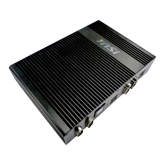
Overview Thank you for choosing the 9A29, an excellent indus- trial computer system from MSI. The MS-9A29 eliminates the noise and the risk of fan’s failure by wide heatsink as fanless solution. Fur- thermore, it supports VESA wall-mount interface for... -
Page 12: Packing Contents
▍ ▍ Overview Overview Packing Contents Power Adapter MS-9A29 System Power Cord Mounting Brackets SATA Power & Signal Cable Driver/Utility Disc User’s Manual (Optional) ■ Please contact us immediately if any of the item is damaged or missing. ■ The picture is for your reference only and your packing contents may slightly... -
Page 13: System Overview
MS-9A29 MS-9A29 System Overview Top View Rear View WLAN Antenna Connector (Optional) This connector allows you to connect an external antenna for wireless LAN. -
Page 14: Hdmi Port
▍ ▍ Overview Overview Line-Out Jack This connector is provided for headphones or speakers. Power Jack The power adapter converts AC power to DC power for this jack.Power sup- plied through this jack supplies power to the system.To prevent damage to the system, always use the supplied power adapter. -
Page 15: Front View
MS-9A29 MS-9A29 Front View Serial Port The serial port is a 16550A high speed communications port that sends/ re- ceives 16 bytes FIFOs. You can attach a serial mouse or other serial devices directly to the connector. Power Button Press the power button to turn the system on or off. -
Page 16: System Specifications
▍ ▍ Overview Overview System Specifications ■ Intel Cedarview-D D2550 Chipset ■ Intel NM10 chipset Memory ■ 1 DDR3 800 / 1066MHz Non-ECC SO-DIMM slot ■ Supports the maximum of 4GB ■ 2 Gigabit Fast Ethernet by Intel 82583V controller ■... - Page 17 MS-9A29 MS-9A29 Regulatory ■ FCC Class A, CE, C-Tick, BSMI, RoHS compliant Compliance Environm- ■ Operating Temperature: 0oC to 40oC ■ Storage Temperature: 0oC to 50oC ental ■ Humidity: 10% ~ 90% RH, non-condensing...
-
Page 18: Motherboard Jumper
▍ ▍ Overview Overview Motherboard Jumper JVDD1 JCOMP1/2 JVDD2 JBAT1... - Page 19 MS-9A29 MS-9A29 Backlight Pinheader & LVDS Power Jumper: JVDD1, JVDD2 The backlight connector is provided for LCD backlight options while the LVDS power jumper allows users to select the operation voltage of the LVDS flat panel. JVDD1 LVDS Power Jumper...
- Page 20 ▍ Overview Serial Port Power Jumper: JCOMP1, JCOMP2 These jumpers specify the operation voltage of the onboard serial ports. JCOMP1/2 +12V (for COM1/2) AT/ATX Select Jumper: JAT1 This jumper allows users to select between AT and ATX power. JAT1 (Default) 1-10...
-
Page 21: Chapter 2 System Setup
Chapter 2 System Setup This chapter provides you with the information on hardware setup procedures. While doing the installa- tion, be careful in holding the components and follow the installation procedures. For some components, if you install in the wrong orientation, the components will not work properly. -
Page 22: Installation Tools
▍ System Setup Installation Tools A Phillips (crosshead) screwdriver and a flathead screw- driver, can be used to do most of the installation. Choose one with a magnetic head would be better. Pliers, can be used as an auxiliary tool to connect some connectors or cables. -
Page 23: Removing The Cover
MS-9A29 Removing the Cover 1. Place the system horizontally on a flat and steady surface. Locate and remove the screws that secure the system cover. 2. Slide the cover carefully sidewards and remove it from the system. -
Page 24: Installing Memory
▍ System Setup Installing Memory 1. Locate the memory slot. 2. Align the notch on the memory with the key on the slot and insert the memory into the slot at a 45-degree angle. 3. Push the memory gently downwards until the slot clips click and lock the memory in place. - Page 25 MS-9A29 Important • You can barely see the golden finger if the DIMM is properly inserted in the DIMM slot. • To uninstall the DIMM, flip the slot clips outwards and the DIMM will be released instantly.
-
Page 26: Installing The Wireless Lan Card (Optional)
▍ System Setup Installing the Wireless LAN Card (Optional) 1. Locate the Mini PCIe slot. Remove the Mini PCIe card screw preinstalled on the motherboard. 2. Insert the wireless LAN card into the slot at a 45-degree angle. 3. Push the card gently downwards and fasten it with a screw. -
Page 27: Installing The Msata Card (Optional)
MS-9A29 Installing the mSATA Card (Optional) 1. Locate the mSATA slot. Remove the mSATA card screw preinstalled on the motherboard. 2. Insert the mSATA card into the slot at a 45- degree angle. 3. Push the card gently downwards and fasten it... -
Page 28: Installing The Hard Disk Drive
▍ System Setup Installing the Hard Disk Drive 1. Flip over the system cov- er and locate the HDD bracket. Remove the sticker film to uncover the thermal paste. 2. Insert the HDD into the HDD bracket with screw holes aligned. - Page 29 MS-9A29 3. Tighten the screws to fix the HDD to the bracket. Important Please make sure the HDD is properly and completely fixed to the bracket. 4. Connect the SATA signal & power cable to the HDD. 5. Connect the SATA signal &...
-
Page 30: Installing Mounting Brackets
▍ System Setup Installing Mounting Brackets 1. Flip over the system and locate the bracket screw holes. 2. Place the brackets along the sides with screw holes aligned. 3. Fasten the screws to fix the brackets. 2-10... -
Page 31: Chapter 3 Bios Setup
Chapter 3 BIOS Setup This chapter provides information on the BIOS Setup program and allows you to configure the system for optimum use. You may need to run the Setup program when: ■ An error message appears on the screen during the system booting up, and requests you to run SETUP. -
Page 32: Entering Setup
▍ BIOS Setup Entering Setup Power on the computer and the system will start POST (Power On Self Test) process. When the message below appears on the screen, press <DEL> or <F2> key to enter Setup. Press <DEL> or <F2> to enter SETUP If the message disappears before you respond and you still wish to enter Setup, restart the system by turning it OFF and On or pressing the RESET button. -
Page 33: Control Keys
MS-9A29 Control Keys ← → Select Screen ↑ ↓ Select Item Enter Select Change Option General Help Previous Values Optimized Defaults Save & Exit Exit Getting Help After entering the Setup menu, the first menu you will see is the Main Menu. -
Page 34: The Menu Bar
▍ BIOS Setup The Menu Bar ▶ Main Use this menu for basic system configurations, such as time, date, etc. ▶ Advanced Use this menu to set up the items of special enhanced features. ▶ Boot Use this menu to specify the priority of boot devices. ▶... -
Page 35: Main
MS-9A29 Main ▶ System Date This setting allows you to set the system date. The date format is <Day>, <Month> <Date> <Year>. ▶ System Time This setting allows you to set the system time. The time format is <Hour> <Minute> <Second>. -
Page 36: Advanced
▍ BIOS Setup Advanced ▶ Full Screen Logo Display This BIOS feature determines if the BIOS should hide the normal POST messages with the motherboard or system manufacturer’s full-screen logo. When it is enabled, the BIOS will display the full-screen logo during the boot-up sequence, hiding normal POST messages. - Page 37 MS-9A29 ▶ CPU Configuration ▶ Hyper-Threading The processor uses Hyper-Threading technology to increase transac- tion rates and reduces end-user response times. The technology treats the two cores inside the processor as two logical processors that can execute instructions simultaneously. In this way, the system perfor- mance is highly improved.
- Page 38 ▍ BIOS Setup ▶ Super IO Configuration ▶ Serial Port 1/ 2/ 3/ 4 Configuration This setting enables/disables the specified serial port. ▶ Change Settings This setting is used to change the address & IRQ settings of the specified serial port. ▶...
- Page 39 MS-9A29 ▶ Hardware Health Configuration These items display the current status of all monitored hardware devices/com- ponents such as voltages, temperatures and all fans’ speeds. ▶ PCI/PCIE Device Configuration ▶ PCI Latency Timer This item controls how long each PCI device can hold the bus before...
- Page 40 ▍ BIOS Setup duct transactions for a longer time and thus improve the effective PCI bandwidth. For better PCI performance, you should set the item to higher values. ▶ Legacy USB Support Set to [Enabled] if you need to use any USB 1.1/2.0 device in the op- erating system that does not support or have any USB 1.1/2.0 driver installed, such as DOS and SCO Unix.
-
Page 41: Boot
MS-9A29 Boot ▶ Boot Option #1 / #2 / #3 This setting allows users to set the sequence of boot devices where BIOS attempts to load the disk operating system. ▶ Hard Drive BBS Priorities This setting allows users to set the priority of the specified devices. First press <Enter>... -
Page 42: Security
▍ BIOS Setup Security ▶ Administrator Password Administrator Password controls access to the BIOS Setup utility. ▶ User Password User Password controls access to the system at boot and to the BIOS Setup utility. 3-12... - Page 43 MS-9A29 ▶ Serial Port Console Redirection ▶ Console Redirection Console Redirection operates in host systems that do not have a moni- tor and keyboard attached. This setting enables/disables the opera- tion of console redirection. When set to [Enabled], BIOS redirects and sends all contents that should be displayed on the screen to the serial COM port for display on the terminal screen.
- Page 44 ▍ BIOS Setup where the sending device is capable of sending data much faster than the receiving device can receive it. ▶ VT-UTF8 Combo Key Support This setting enables/disables VT-UTF8 Combo Key Support. ▶ Recorder Mode, Resolution 100x31 These settings enable/disable the recorder mode and the resolu- tion 100x31.
-
Page 45: Chipset
MS-9A29 Chipset ▶ IGFX - Boot Type Use the field to select the type of device you want to use as the boot display of the system. ▶ LCD Panel Type This setting allows you to set the resolution of the LCD panel. -
Page 46: Power
▍ BIOS Setup Power ▶ Restore AC Power Loss This setting specifies whether your system will reboot after a power failure or interrupt occurs. Available settings are: [Power Off] Leaves the computer in the power off state. [Power On] Leaves the computer in the power on state. [Last State] Restores the system to the previous status before power failure or interrupt occurred. - Page 47 MS-9A29 ** Advanced Resume Events Control ** ▶ USB from S3/S4 The item allows the activity of the USB device to wake up the system from S3/S4 sleep state. ▶ PCIE/PCI PME This field specifies whether the system will be awakened from power saving modes when activity or input signal of onboard PCIE/PCI PME is detected.
-
Page 48: Save & Exit
▍ BIOS Setup Save & Exit ▶ Save Changes and Exit Save changes to CMOS and exit the Setup Utility. ▶ Discard Changes and Exit Abandon all changes and exit the Setup Utility. ▶ Restore Defaults Restore the factory defaults. ▶... -
Page 49: Appendix Wdt & Gpio
Appendix WDT & GPIO This appendix provides the sample codes of WDT (Watch Dog Timer) and GPIO (General Purpose Input/ Output). -
Page 50: Wdt Sample Code
▍ WDT & GPIO WDT Sample Code SIO_INDEX_Port equ 04Eh SIO_DATA_Port equ 04Fh SIO_UnLock_Value equ 087h SIO_Lock_Value equ 0AAh WatchDog_LDN equ 007h WDT_UNIT equ 60h ;60h=second, 68h=minute, 40h=Disabled Watchdog timer WDT_Timer equ 30 ;ex. 30 seconds Sample code: ;Enable config mode dx, SIO_INDEX_Port al, SIO_UnLock_Value dx, al... -
Page 51: Gpio Sample Code
MS-9A29 GPIO Sample Code GPI 0 ~ GPI 3 GPI 0 GPI 1 GPI 2 GPI 3 IO Address 50Ch 50Ch 50Ch 50Ch SIO GPIO Register Sample code GPO 0 ~ GPO 3 GPO 0 GPO 1 GPO 2... - Page 52 NOTE...
Need help?
Do you have a question about the MS-9A29 and is the answer not in the manual?
Questions and answers