Table of Contents
Advertisement
Advertisement
Table of Contents

Subscribe to Our Youtube Channel
Related Manuals for Teldat VisorALARM PLUS 2U

Summary of Contents for Teldat VisorALARM PLUS 2U
- Page 1 VisorALARM PLUS 2U Installation Manual Doc. DM374-I Rev. 1.0 May, 2007...
-
Page 2: Table Of Contents
INDEX CHAPTER 1 INTRODUCTION ...........................1 ALARM PLUS 2U I ....................2 ISOR NTRODUCTION ..........................3 NSTALLATION CENARIO ............................6 PERATING 3.1. Monitoring ............................6 3.2. Sending of Alarms ..........................7 ..........................9 DDITIONAL EATURES ......................10 ONFIGURATION AND ANAGEMENT CHAPTER 2 INSTALLATION ..........................11 ............................12 NTRODUCTION 1.1. General installation conditions......................12 1.2. -
Page 3: Chapter 1 Introduction
Chapter 1 Introduction... -
Page 4: Visoralarm Plus 2U Introduction
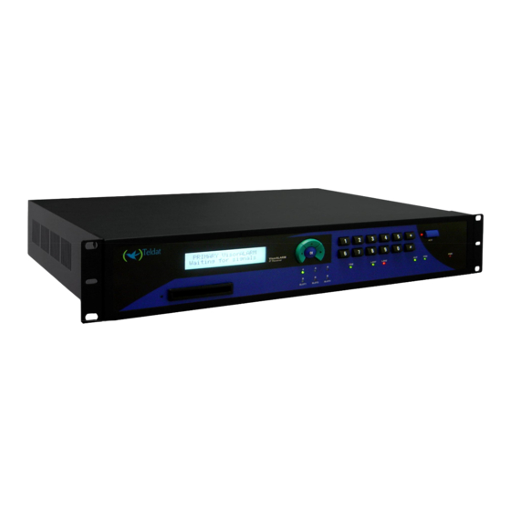
The VisorALARM PLUS 2U is supplied with a display and a keypad in order to validate the signals received and monitor the device. The VisorALARM PLUS 2U includes interfaces to connect to an Automation Software and to a printer. -
Page 5: Installation Scenario
2. Installation Scenario A traditional security scenario consists of a control panel (CP), located in the client environment and an alarm receiver center (ARC) located in the security company’s control center. The CP contains a group of sensors which trigger a series of alarms or events which, when produced, are sent to the ARC to be processed. - Page 6 Network backup permits you to add a second VisorALARM PLUS 2U configured as backup and which would be a second option of sending alarms in cases where the main VisorALARM PLUS 2U fails. If the probe over the main fails, the mIP/IPDACT (from release 2.2 onwards) tries to establish communications with the backup...
- Page 7 It’s advisable that the VisorALARM PLUS 2U devices have different gateways and different Internet access servers to ensure efficient network backup. Figure 4. Operating scenario with network backup VISORALARM - Introduction Doc.DM374-I Ver. 1.0 I - 5...
-
Page 8: Operating Mode
From this point on, the mIP/IPDACT will try to re-establish communications with both the main Teldat VisorALARM PLUS 2U as well as the backup, if there is one. As soon as this is re- established with either of the two VisorALARM PLUS 2U, the mIP/IPDACT will once more intercept the telephone line. -
Page 9: Sending Of Alarms
399 restore code to indicate the main device is up. Both the main and the backup VisorALARM PLUS 2U can have communication problems (Loss of central polling) and consequently pass to a down state sending code event 396 for main and 398 for backup. - Page 10 2 seconds, this carries on resending a configured number of times (between 5 and 10), after which connection with the Teldat VisorALARM PLUS 2U is assumed lost. As in the case of supervision where the alarm send fails, this can be sent again this time to the backup VisorALARM PLUS 2U if this functionality is configured.
-
Page 11: Additional Features
The code for this event is configurable, default being 633 (Module Added). In order to maintain and update the registered mIP/IPDACTs base, the Teldat VisorALARM PLUS 2U has commands available to remotely update one or multiple configuration parameters used by the mIP/IPDACTs. -
Page 12: Configuration And Management
The default login and password for the manager user is “manager/24680”. The VisorALARM PLUS 2U is supplied with a display and keypad. The display is the means through which the user can access the signal information. The signals can be validated by using the keypad. -
Page 13: Chapter 2 Installation
Chapter 2 Installation... -
Page 14: Introduction
1. Introduction The IP VisorALARM PLUS 2U receiver is designed to be both a desktop and a rack device. In either case, in order to achieve correct installation, please follow the recommendations given below: BEFORE CONNECTING THE DEVICE PLEASE READ THE FOLLOWING INSTRUCTIONS CAREFULLY. - Page 15 VISORALARM - Installation Doc.DM374-I Ver.1.0 II - 13...
-
Page 16: Connection
Figure 5. 19” rack installation and device power connections WARNING: Electric supply current, telephone and communication cables are dangerous. To prevent electric shock while installing, moving or opening the device covers, cables should be disconnected and connected as follows: To connect the VisorALARM PLUS To disconnect the VisorALARM PLUS •... - Page 17 If there is no connection, the LED will light up in red. d) VisorALARM Expansion Card The VisorALARM PLUS 2U is supplied with three slots where three VisorALARM Expansion Cards can be plugged in (Labeled as VA-UD in the rear panel). The device is supplied with one VA-UD in the factory configuration.
- Page 18 UPS device. e) Configuration connection The IP VisorALARM PLUS 2U receiver routers have a female DB-9 connector in the rear panel referred to as “AUX” which provides access to the device local console for configuration and monitoring purposes.
-
Page 19: Switching On The Device
Figure 5. Connection for configuration/monitoring via console The configuration of the terminal must be: - Speed: 9600 bps - Eight data bits - No parity bit - One stop bit - No type of flow control Also expressed as 9600 8N1. The connection to the configuration port can be carried out with DB-9 female-DB-9 male cable provided with the equipment. - Page 20 ************************************************** ************************************************** ************************************************** BOOT CODE VERSION: 01.10 Oct 30 2006 17:17:43 gzip Oct 30 2006 17:08:44 P.C.B.: 75 MASK:0A01 Microcode:0070 START FROM FLASH BIOS CODE DUMP..... BIOS DATA DUMP..End of BIOS dump Boot-stack used: 0x00000788 Boot-stack free: 0x00001878 BIOS CODE VERSION: 01.10 CLK=294912 KHz BUSCLK=65536 KHz PCICLK=32768 KHz...
-
Page 21: Chapter 3 Configuration
Chapter 3 Configuration... -
Page 22: Introduction
1. Introduction The aim of this chapter is to provide guidelines for the user regarding the VisorALARM PLUS 2U configuration process to ensure it runs correctly. The basic VisorALARM PLUS 2U function is to receive alarms from the mIP/IPDACT devices via an IP network, and send to an automation software through a serial interface emulating one of the supported receivers. -
Page 23: Common Configuration
2. Common configuration The VisorALARM PLUS 2U receiver is shipped from factory with a default configuration. This is the basic configuration that allows the manager to come into operation. For that reason, the installation process starts from this configuration. The first step is to access the device configuration menu in order to adapt some configuration parameters to the client scenario. - Page 24 The device prompts the user for the login and password to gain access to the configuration. The factory configuration for the login/password is “manager/24680”. Press any key to get started User: manager Password: ***** Teldat (c)2001-2006 Router model VISORALARM-PLUS US 6 120 CPU MPC8260 S/N: 472/05898 2 LAN, 4 WAN Lines CIT software version: 10.6.27-Alfa Nov 17 2006 17:05:13...
- Page 25 Teldat device. This parameter is optional; the following example shows you how to configure this using PRIMARY as the device name. Where you have a configuration with another VisorALARM PLUS 2U as network backup, it is advisable to assign names to the devices to identify the main VisorALARM PLUS 2U and the backup.
- Page 26 Teldat recommends you to take the factory configuration and save it in a file. This configuration can be used in cases where the manager wants the device to start from scratch. The way to get the factory configuration is by using the “show configuration” command and to copy it over to the clipboard.
-
Page 27: Changing The Ip Protocol Configuration
3. Changing the IP Protocol Configuration Communications between VisorALARM PLUS 2U and mIPs are carried out by the IP protocol. The factory configuration assigned IP address 192.168.0.200 and mask 255.255.0.0 to the Ethernet interface. In cases where the manager wants to change the IP address to pertain to the IP network, the following steps must be executed. -
Page 28: Configuring The Ntp Client
The NTP protocol is based in a client-server model, where the NTP clients are synchronized with a NTP server that possesses a stable time. In our case the VisorALARM PLUS 2U receiver adopts the client role. There are several public lists of NTP servers, the system manager can choose any of the NTP servers included in those lists to synchronize main and backup receivers (one example of such servers is the Massachusetts Institute of Technology (MIT) with an 18.145.0.30 public address). - Page 29 PRIMARY NTP config>show conf ; Showing Menu and Submenus Configuration ... ; Visor Alarm Router 2 16 Version 10.4.7 protocol source-address 172.24.77.53 peer address 1 18.145.0.30 MAIN NTP config> VISOR ALARM – Configuration Doc.DM374-I Ver.1.0 III - 27...
-
Page 30: Arly Alarm Reception Interface
-- ARLY Interface Configuration -- PRIMARY ARLY-1 Cfg> 5.1. Alarm Receiver The first step is to configure the parameters related to the behavior of the VisorALARM PLUS 2U as receiver. The VisorALARM PLUS 2U is capable of emulating three types of receivers: •... - Page 31 The line number identifies each of the line cards connected to the receiver. In the VisorALARM PLUS 2U, as communication is through an IP network, there are no line cards; however you must configure a line number as the said number is sent from the receiver to the server with the alarms.
-
Page 32: Communicating With The Automation Server
5.3. Communication parameters with the printer Connection to the printer is carried out through an asynchronous serial port. So the communication works correctly, both ends (the VisorALARM PLUS 2U and the printer) must have the same configuration in the serial line. Parameters requiring configuration are: •... -
Page 33: Communicating With The Mip/Ipdacts
Network backup is the possibility of the mIP/IPDACT having a second receiver to send alarms to and keep-alive polls. From the VisorALARM PLUS 2U point of view, network backup consists of two devices, one configured as main and the other as secondary or backup. Both devices should have different gateways and if possible different Internet access providers. - Page 34 VisorALARM PLUS 2U. • sync-port: This is the TCP port that listens in the main VisorALARM PLUS 2U to which the backup VisorALARM PLUS 2U connects each time the configurations need to be synchronized. Synchronizations are always produced each time either of the two VisorALARM PLUS 2U starts up and periodically once both are operating.
-
Page 35: Maintenance Receiver
5.7. User Configurable Events As previously mentioned, there are various situations where the VisorALARM PLUS 2U generates alarms which are sent to the automation software to notify the operator of the existence of certain situations. The event codes used are configurable, through the commands given below. -
Page 36: Configuration Pattern
To simplify the mIP/IPDACT installation task, the VisorALARM PLUS 2U has a feature which permits you to install an mIP/IPDACT by configuring a reduced set of parameters. Through a “register” operation you then receive the rest of the configuration from the VisorALARM PLUS 2U. The complete process is described below: •... - Page 37 The available options are all the mIP/IPDACT configuration parameters. These are detailed below. Some of the parameters the mIP/IPDACT uses with the main VisorALARM PLUS 2U, others with the backup device and others affect the maintenance VisorALARM PLUS 2U. The rest are common application.
- Page 38 Subsequently the commands to configure a configuration pattern, with identifier 1, are shown. In this said pattern the VisorALARM PLUS 2U IP address and UDP port parameters have not been configured as they are already configured in the mIP/IPDACT (these are required for installation purposes) and do not require changing.
-
Page 39: Upload/Download Operation
Usually, the system is composed by two workstations running Upload/Download software and connected through a Serial Port to a VisorALARM PLUS 2U receiver (VA-UD com1 and VA-UD com2) by means of the supplied Micro DB9 to DB9 cables. The VisorALARM is connected to Internet as usual. - Page 40 PRIMARY ARLY-2 Cfg>mip <accountNumber> subscriber-telephone <phoneNumber> Usually, it is necessary to program the Upload/Download software with a specific set of AT Initialization Strings to be used with VisorALARM PLUS 2U receivers. The next table shows the initialization strings for the supported Control Panels.
- Page 41 General Electric Comax Initialization String: F1S0=0S10=250S7=60S9=1 HUNTER PRO 32 Init. String (callback): F1S0=1S10=250S7=60S9=1 PIMA Default Initialization: E0V1S0=0 Windows Infinite Setup Electronic Line Initialization modem strings for supported Upload/Download software packages VISOR ALARM – Configuration Doc.DM374-I Ver.1.0 III - 39...
-
Page 42: Final Adjustments
6. Final Adjustments To finalize this process, we recommend enabling the ARLY interface events. These will help when diagnosing possible problems. To do this, execute the commands shown below: PRIMARY ARLY-1 Cfg>exit PRIMARY Config>event -- ELS Config -- PRIMARY ELS config>enable trace subsystem arly all PRIMARY ELS config>exit PRIMARY Config>... -
Page 43: Example
The aim of this example is to provide a view on the whole of the mIP/IPDACT installation process and system behavior during normal operation. The idea is as follows: a traditional security scenario wishes to adopt the Teldat solution which permits alarms from the control panel to be sent over IP and similarly supervise the connection. - Page 44 IP and UDP. As regards IP, an IP address and mask must be configured in the VisorALARM PLUS 2U. In this example, the address is public and is the same as the one configured in the mIP/IPDACTs. A route is aggregated so that all the traffic is routed through the access gateway.
- Page 45 ARLY-1 Cfg>serial-parameters parity even ARLY-1 Cfg>serial-parameters stop-bits 2 ARLY-1 Cfg> Up to this point, everything configured can be viewed through the SHOW CONFIG command, which for the main VisorALARM PLUS 2U is: VISOR ALARM – Configuration Doc.DM374-I Ver.1.0 III - 43...
- Page 46 ; -- Internet protocol user configuration -- address ethernet0/0 172.28.1.30 255.255.0.0 address ethernet0/0 215.99.32.3 255.255.255.0 route 0.0.0.0 0.0.0.0 172.28.1.1 1 exit dump-command-errors ; --- end --- Config> And for the backup VisorALARM PLUS 2U, VISOR ALARM – Configuration Doc.DM374-I Ver.1.0 III - 44...
- Page 47 Config>show config ; Showing System Configuration for access-level 15 ... ; VISORALARM-PLUS US Router 6 120 Version 10.6.27 log-command-errors no configuration description "Default configuration: VisorALARM standard" set data-link arly serial0/0 set data-link sepi serial0/1 set data-link modem-emu serial1/0 set data-link modem-emu serial1/1 set sram-size 1024 cfg-mode binary ;...
- Page 48 Are you sure to restart the system(Yes/No)? y At this point you can check various aspects, both for the main and the backup devices. To simplify this, the checks are indicated for the main VisorALARM PLUS 2U; however they are also directly applicable to the backup.
- Page 49 ARLY-1 Cfg>cfg-pattern 10 bck-receiver-ip 215.99.32.3 ARLY-1 Cfg>cfg-pattern 10 bck-keep-alive-timer 5 ARLY-1 Cfg>cfg-pattern 10 bck-keep-alive-retries 2 ARLY-1 Cfg>cfg-pattern 10 bck-keep-alive-retries-time 2 ARLY-1 Cfg> Subsequently the configuration, for the main VisorALARM PLUS 2U for example, will be: VISOR ALARM – Configuration Doc.DM374-I Ver.1.0 III - 47...
- Page 50 CRA Config>show config ; Showing System Configuration for access-level 15 ... ; VISORALARM-PLUS US Router 6 120 Version 10.6.27 log-command-errors no configuration description "Default configuration: VisorALARM standard" set data-link arly serial0/0 set data-link sepi serial0/1 set data-link modem-emu serial1/0 set data-link modem-emu serial1/1 set sram-size 1024 cfg-mode binary ;...
- Page 51 Subsequently, the installer must proceed to the register using the password (99887766). If the ARLY interface events are enabled in the VisorALARM PLUS 2U, check for the arrival of the register petition and the sending of the configuration to the mIP/IPDACT, as well as the event sending which notifies the installation of a new mIP/IPDACT.
- Page 52 VisorALARM PLUS 2U normal functionality On receiving the configuration from the VisorALARM PLUS 2U, the mIP/IPDACT tries to connect. If the ARLY interface events are enabled in the VisorALARM PLUS 2U, the connection petition (cntct) arrival and the sending of the response is checked.
- Page 53 +09/02/03 10:36:35 ARLY.014 RSPVSN accnt 101234 TMOUT 09/02/03 10:36:35 ARLY.019 STOR save, 499 free 09/02/03 10:36:35 ARLY.008 FMS st 2 ev 8 09/02/03 10:36:35 ARLY.005 SL Tx 56 181234E35000000 09/02/03 10:36:35 ARLY.004 SL Rx ACK 09/02/03 10:36:35 ARLY.008 FMS st 4 ev 1 09/02/03 10:36:35 ARLY.020 STOR delete, 500 free The next figure shows the process of sending supervision packets from a mIP/IPDACT to a...
- Page 54 Monitoring the mIP/IPDACT state at this point through the LIST MIP INFORMATION monitoring command shows that the connection has been lost. VISOR ALARM – Configuration Doc.DM374-I Ver.1.0 III - 52...
- Page 55 Subs Phone: ARLY-1+ If connection between the mIP/IPDACT and the VisorALARM PLUS 2U is recovered (e.g. by connecting the mIP/IPDACT to the LAN again), you can check reception for a contact and a keep- alive frame and the responses, and the connection recovery through the ARLY interface events. This is displayed through the LIST MIP INFORMATION monitoring command.
- Page 56 09/02/03 09:59:02 ARLY.020 STOR delete, 500 free As you can see, the alarm is received in the VisorALARM PLUS 2U and retransmitted to the Automation Sw complying with the emulated receiver format. If the connection with the Automation Sw is not active, the alarm is stored until the connection has been reestablished and then sent.
- Page 57 − POLL TIME • When the backup VisorALARM PLUS 2U receives the indication of a change in configuration, it establishes a TCP connection with the main receiver through which the changes in the configurations are exchanged. • When the change in the configuration has been made in the backup, the average time to start...
- Page 58 One example of synchronization is when an mIP/IPDACT registration is produced. In this case the VisorALARM PLUS 2U dynamic configuration is modified. The traces for the main VisorALARM PLUS 2U when the synchronization timer has completed are as follows: 03/04/05 17:44:10 ARLY.032 MAIN sync: Update commited.
-
Page 59: Chapter 4 Appendices
Chapter 4 Appendices... -
Page 60: Troubleshooting
Check that the terminal has the correct port configured. displaying garbage Check that the terminal configuration is 9600 8N1. The device does not initialize and Contact Teldat’s Technical Service Department. the console displays the WARM- UP text. The device is very slow in Contact Teldat’s Technical Service Department. -
Page 61: Connecting The Connectors
RJ45 LAN RJ45 PIN Ethernet Tx+(input) Tx-(input) Rx+(output) Rx-(output) 2.2. AUT/PRN Connectors NOTE: Cables used for multi-purpose Teldat drivers must not be used in these connections. You must use end-to-end pin-to-pin connector cables. STANDARD DB25 V.24 Connector Signal Ground ExTxC... -
Page 62: Visoralarm Expansion Card Connectors
RA:2A Input1 +12V/-12V Input2 +12V/-12V WARNING: For UL Listed installation the equipments connected to COM1/COM2 connectors and I/O connector are restricted to be in the same room as the VisorALARM PLUS 2U VISORALARM - Appendices Doc.DM374-I Ver.1.0 IV - 60... -
Page 63: Aux Port Connections
Signal Joined pines 1-4-6 Joined pines WARNING: For UL Listed installation the equipments connected to AUX Port connector are restricted to be in the same room as the VisorALARM PLUS 2U VISORALARM - Appendices Doc.DM374-I Ver.1.0 IV - 61... -
Page 64: Technical Specifications
3. Technical Specifications Hardware Architecture PROCESSOR Motorola MPC8270, at 50, 66 or 80 MHz, depending on version MEMORY 32, 64 128 or 256 Mbytes of SDRAM, depending on version STORAGE UNIT FLASH Memory, 4, 8 or 16 Mbytes depending on version EEPROM 2 Kbytes, NVRAM 128 Kbytes LAN Interface PROTOCOLS... -
Page 65: Ul Compliance Installation
24 hours. c) UPS The VisorALARM PLUS 2U must have a UL listed UPS suitable for fire-protective signaling capable of allowing the receiver to operate during 15 minutes. -
Page 66: Installation Requirements
Employs the CFB code which is certified by NIST, Cert No. 280. 2. For the 200 sec. supervision, the system "polls" the VisorALARM PLUS 2U receiver via packet switched data network. Note, 90 sec. Supervision is required for commercial fire applications. -
Page 67: Configuration Requirements
2. The control panel shall be programmed to transmit the required opening and closing signals. c) BURGLAR ALARM (PROPRIETARY) DACT, PACKET SWITCHED DATA NETWORK 1. Same as Central Station. 2. The minimum platform redundant computer system including the receiver must be used to display and record panel status changes. - Page 68 It is essential that you have a spare device thus permitting you to substitute the VisorALARM PLUS 2U in a maximum period of time of 30 minutes. To do this, it is vital you have a backup copy of the VisorALARM PLUS 2U SmartCard so when this is inserted into the substitute device, the configuration is identical to the original device.
- Page 69 • Configure the ‘link-test-timer’ parameter for both the main receiver and the backup to a value between 60 and 200 seconds. • It is essential that you have a spare device thus permitting you to substitute the VisorALARM in a maximum period of time of 30 minutes. To do this, it is vital you have a backup copy of the VisorALARM SmartCard so when this is inserted into the substitute device, the configuration is identical to the original device.
-
Page 70: Alarm Printing Format
5. Alarm printing format The format to print using 40 columns in the VisorALARM PLUS 2U includes the following fields: MM/DD hh:mm:ss Date and time of the event AAAA: Account code P: Qualificator, E= New event or opening; R=Restoration or closing; P=Previous event CCC: Type of event and code for this XX: Number of group or partition. -
Page 71: Automation Software
6. Automation Software The frame formats exchanged with the automation software through the serial port for each of the emulated receivers are as follows: 6.1. Frame formats a) Sur-gard Format MLR2000 • 5RRLLLs18AAAAQXYZGGCCC[T] Where: RR: Receiver number LLL: Line number s: Space 18: Contact-Id format identifier AAAA: Four-digit account code... - Page 72 • Heartbeat 1011sssssssssss@ssss[T] Where: s: Space @: Supervision character [T]: 14 hex character as terminator b) Radionics 6500 Format • [H]aRRLsAAAA18QXYZGGCCC[T] Where: [H]: 20 hex character (space) as header ‘a’: Start indicator for Contact-Id message RR: Receiver number L: Line number s: Space 18: Contact-Id format identifier AAAA: Four-digit account code...
-
Page 73: Sis Software
ADEMCO 685 6.2. SIS Software VisorALARM PLUS 2U is compatible with the SIS automation software for the three emulation modes (Sur-gard, Radionics 6500 and Ademco 685). To configure the automation software, simply select the type of receiver from among these three and configure the ‘protocol’ field from the group of VisorALARM PLUS 2U alarm-receiver parameters and configure the value corresponding to the selected emulated receiver.
Need help?
Do you have a question about the VisorALARM PLUS 2U and is the answer not in the manual?
Questions and answers