Table of Contents
Advertisement
Advertisement
Table of Contents

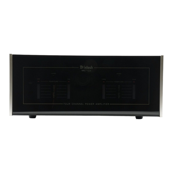
Summary of Contents for McIntosh MC7104
- Page 1 MC7104 POWER AMPLIFIER...
- Page 3 MC7104 POWER AMPLIFIER...
- Page 4 1. Read all instructions - Read the safety and operating instructions before operating the instrument. IMPORTANT 2. Retain Instructions - Retain the safety and operating instructions for future reference. 3. Heed warnings - Adhere to warnings and operating instructions. SAFETY 4.
-
Page 5: Table Of Contents
Your Mclntosh Authorized Service Agency can expedite repairs when you provide them with the Service Contract. SERVICE CONTRACT TABLE OF INTRODUCTION CONTENTS OPERATING CONFIGURATIONS HOW TO INSTALL THE MC7104 FRONT PANEL DISPLAYS REAR PANEL AND DHOW TO MAKE CONNECTIONS 7, 8, 9, 10 SPEAKER-AMPLIFIER CONNECTION DIAGRAMS 11, 12 SPECIFICATIONS... -
Page 6: Service Contract
TAKE ADVANTAGE OF 3 YEARS OF CONTRACT SERVICE. . . FILL IN THE APPLICATION NOW. Your C39 Audio/Video Control Center will give you many years of satisfactory performance. If you have any questions, please contact, Mclntosh Laboratory Inc. 2 Chambers Street Binghamton, New York 13903-2699 Phone: 607-723-3512 An application for A THREE YEAR SERVICE CONTRACT is included with this manual. -
Page 7: Introduction
Home Theater System. Use the stereo amplifier for the left and right front speakers. Use the MC7104 with a bridged channel pair with 300 watts for the center channel and the two remaining 100 watt channels for the surround speakers. -
Page 8: How To Install The Mc7104
The MC7104 can be placed upright on a table or shelf, standing on its four plastic feet. It can HOW TO also be installed in a Mclntosh L84 cabinet. Follow the installation instructions included with the INSTALL L84. THE MC7104 The MC7104 is designed to be easily installed in a cabinet of your choice. -
Page 9: Rear Panel And Dhow To Make Connections
DIN cable from the first MC7104, MULTI - ROOM OUT connector to the MULTI - ROOM IN connector on the second MC7104. When Zone 3 is selected, speaker relays for channels 1 and 2 of the second amplifier are turned on. When Zone 4 is selected, channels 3 and 4 are selected. The second MC7104 can then be used to supply audio power to remote zones 3 and 4. - Page 10 NORMAL (STEREO) Mode: Adjust the individual channel level controls to the 2.5 Volt setting when the MC7104 is used with Mclntosh Preamplifiers, Control Centers or Remote Control Systems. For other applications you may wish to increase or decrease the settings as desired.
- Page 11 12. AC POWER CABLE Connect the MC7104 power cable to a 50/60Hz , 120 volt AC wall outlet or a Power Control Relay. The power outlet should be capable of handling up to 8 amperes or 960 watts. Do not connect the cable to an AC outlet on the rear panel of a Preamplifier or Control Center.
- Page 12 Connect a cable from the negative (-) terminal of the loudspeaker being used with bridged pair channels 1 and 2, to the MC7104 negative (-) MONO/BRIDGED terminal for channels 1 and 2. Connect a cable from the positive (+) loudspeaker terminal to the MC7104 positive (+) MONO/BRIDGED OUTPUT terminal.
-
Page 13: Speaker-Amplifier Connection Diagrams
TO PREAMPLIFIER TO PREAMPLIFIER SPEAKER- AMPLIFIER PLACE MODE SWITCH PLACE MODE SWITCH IN NORMAL IN NORMAL CONNECTION NORMAL NORMAL DIAGRAMS MONO (BRIDGED) MONO (BRIDGED) 4 OHM 4 OHM 4 OHM 4 OHM SPEAKER SPEAKER SPEAKER SPEAKER CHANNEL 1 CHANNEL 3 CHANNEL 2 CHANNEL 4 TO PREAMPLIFIER... - Page 14 TO PREAMPLIFIER TO PREAMPLIFIER SPEAKER- AMPLIFIER PLACE MODE SWITCH PLACE MODE SWITCH IN MONO (BRIDGED) IN MONO (BRIDGED) CONNECTION NORMAL NORMAL DIAGRAMS MONO (BRIDGED) MONO (BRIDGED) 4 OHM 4 OHM SPEAKER SPEAKER CHANNELS CHANNELS 3 AND 4 1 AND 2...
-
Page 15: Specifications
POWER OUTPUT, 4 CHANNELS SPECIFICATIONS 100 watts into 4 ohm loads, minimum sine wave continuous average power output per channel, all channels operating. The RMS voltage is 20V across 4 ohms. POWER OUTPUT, MONO/BRIDGED PAIRS 200 watts into 8 ohm loads, minimum sine wave continuous average power output per channel pair. - Page 16 WIDE BAND DAMPING FACTOR SPECIFICATIONS 8 ohm loads, 200 4 ohm loads, 100 POWER REQUIREMENTS 120 volts, 50/60HZ, 3 Amperes UL/CSA DIMENSIONS 17-1/2 inches (44.5cm) W x 7-1/16 inches (17.9cm) H x 20 inches (50.8cm) D WEIGHT 48 pounds (21.8Kg) net, 67 pounds (30.4Kg) shipping...
-
Page 17: Custom Installation Diagrams
CUSTOM INSTALLATION DIAGRAM RECOMMENDED VENTILATION CUTOUT IN MOUNTING SHELF... -
Page 18: Rear Panel Fold Out
The numbers refer to the paragraphs on pages 7 through 10. 04033600...


Need help?
Do you have a question about the MC7104 and is the answer not in the manual?
Questions and answers